Defender Press Brake Guarding System Operation Manual
LS-CS-M-069
Page 20
Original Language Version: 1.04
Released:
01/04/2020
5.4.1
Status and Action Windows
The Status window informs the operator of the current status of the Defender system, and
the machine it is guarding. The information provided by the Status screen includes:
•
Operating Mode
. The guard mode currently selected (Normal, Tray, Tray 2, Field
Muted) is displayed during normal operation. This message will be overwritten if an
error/fault condition occurs.
•
Mute Status
. The Status window turns red whenever the guarding is muted, to clearly
indicate to the operator that guarding is inactive.
•
Error/Fault Messages
. If the Defender system detects an error or fault condition the
operator will be alerted by the Status window. In most cases this will be a short
message that describes the error/fault condition.
•
Condition Code
. The PGS-2 Safety Controller displays Condition Codes on its
scrolling LCD panel to communicate actions, errors or faults. These codes are
displayed as a 4-digit hexadecimal code (numbers 1-9, letters A-F) that uniquely
describes a particular condition. This Condition Code is also displayed in the lower
right hand corner of the Status window.
•
Operation Pending
: If the PGS-2 Safety Controller requires that an operation is to
be performed to verify the safety performance of the machine (such as an over run
test) the operator is informed of the upcoming operation in the Status window (and is
also prompted for action by Action window message).
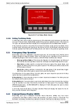
The Action window prompts the operator with the action required to complete the current
operation. For example, if a fault condition occurs, the error message and condition code are
displayed in the Status window, while the Action window prompts the operator to
PRESS
RESET
.
5.4.2
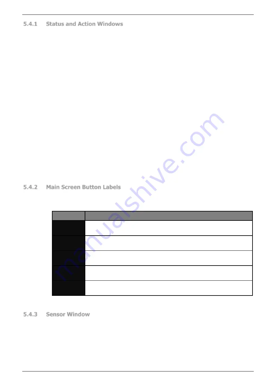
Main Screen Button Labels
The five buttons on the User Interface Panel change function depending upon the current
screen, the Supervisor menu configuration, and the state of the machine. The button labels
for the Main screen are shown in
Label
Button Function
MENU
This leaves the Main screen and enters the Menu screen. See
for an overview of the menu system.
TOOL
SETUP
Leaves the main screen and enters the Tool Setup screen (an access
code is required to enter the Tool Setup screen).
MODE
SELECT
Leaves the Main screen and enters the Mode Select screen, where the
guard modes can be selected.
SET/MUTE
RESET
This button can be used to set or reset the mute point. The button label
changes depending upon the state of the mute point.
INFO
This leaves the main screen and enters the Info Screen. See
for an overview of the menu system.
Table 5-1: Main Screen Buttons
5.4.3
Sensor Window
The Sensor window shows the status of the optical protection from the point of view of the
receiver (the front sensor is to the left of the screen). Symbols in the window show the current
active mode, and the state of the receiver sensors in real time. The general appearance of
the window is shown in
In the following sections the Sensor window will always be shown with the appropriate
symbols for the operating mode being described.