Defender Press Brake Guarding System Operation Manual
LS-CS-M-069
Page 21
Original Language Version: 1.04
Released:
01/04/2020
A
MOS 11mm
STD
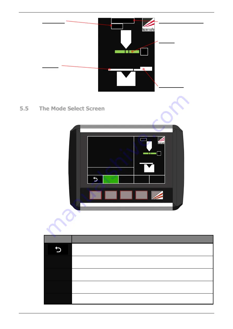
Figure 5-4: Sensor Window
5.5
The Mode Select Screen
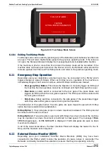
The other screen used in most typical machine operations is the Mode Select screen. This
only differs from the Main screen in the function of the five input buttons.
FIELD
MUTED
GUARD
MODE
MUTE
STOP
BACK
GAUGE
ACTION PRESS FOOT PEDAL
OVERRUN TEST
0000
STATUS
A
STD
Figure 5-5: Mode Select Screen
The buttons are used to select the different guard modes (the modes are detailed in
Sections
Label
Button Function
This leaves the Mode Select screen and returns to the Main screen.
See
for an overview of the menu system.
GUARD
MODE
This button cycles through the guard modes: Normal
→
Tray
→
Tray 2
→
Normal etc.
FIELD
MUTED
If this button is enabled, it toggles the Field Muted mode. The
functionality of this button can be configured in the Supervisor menu.
MUTE
STOP
If this button is enabled, it toggles the Stop at Mute mode. The
functionality of this button can be configured in the Supervisor menu.
BACK
GAUGE
This button toggles the Back Gauge mode.
Table 5-2: Mode Select Screen Buttons
Mute Mode
Indicates the mute mode
option.
Material
This symbol shows that the
guarding is set to Normal
mode. This symbol will
change when Tray or Tray 2
modes are selected.
Mute Off-Set Distance
Shows the mute off-set
distance in millimetres.
Laser A
These symbols show the
status of the
FRONT,
MIDDLE
and
REAR
sensors of the laser
receiver
– green for clear,
red for obstructed.
Back Gauge
Indicates that Back Gauge
mode is enabled.


