background image

Page


21

35

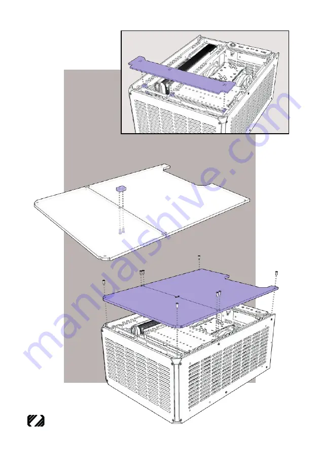
Place cover over front 
fram supports

LAZER3D

PERFORMANCE SFF PC CASES

34

33

(OPTIONAL) - If Top Dual Panel selected, secure the 2 sections of 
Top Panel together with 1 x metal block and 2 x 

M3x8mm

 screw 

in the centre position.

Secure top panel 
to the case with 
8 x 

M3x8mm


Screws

Summary of Contents for LZX-15

Page 1: ...LZX 15 User Manual LAZER3D PERFORMANCE SFF PC CASES ...

Page 2: ...n Panels Assembly 7 Corner Columns 8 10 Internal Frame Assembly 11 Front Case Fans 12 Support Rail Assembly 13 14 PSU GPU Mounting 15 16 Storage Options 17 18 Case Cooling Options 19 Internal PSU Cable 20 Side Panels 21 Top Panel 22 Case Feet 23 24 Vertical Stand Assembly 25 26 Reference Diagrams Page 1 LAZER3D PERFORMANCE SFF PC CASES ...

Page 3: ...Page 2 LAZER3D PERFORMANCE SFF PC CASES SPECIFICATION ...

Page 4: ...se take care when assembling WARNING Do not over tighten the screws when securing the panels as this can reduce thread life NOTE Peel off protective film from BOTH sides of each panel before assembling the case COMPONENT LIST LAZER3D PERFORMANCE SFF PC CASES Page 3 ...

Page 5: ...Page 4 LAZER3D PERFORMANCE SFF PC CASES QUICK ASSEMBLY REFERENCE PLEASE READ THESE INSTRUCTIONS CAREFULLY BEFORE ASSEMBLING THE CASE ...

Page 6: ...PC CASES 1 Don t forget to insert your IO Shield Attach 2x metal blocks to the rear panel with 2x M3x8mm Screws 3 ASSEMBLY TIP Use a PH1 screwdriver with the M3x8 and M3x5 screws 2 Attach I O board to rear panel with 2x M3x6mm Screws ...

Page 7: ...F PC CASES Attach the rear panel to the the base panel with 2x M3x8mm Screws 4 Attach 3x metal blocks to the base panel with 3x M3x8mm Screws Mount Power Button to IO Panel 5 6 7 Attach IO Panel to Rear Panel with 2x M3x8mm Screws ...

Page 8: ...Page 7 LAZER3D PERFORMANCE SFF PC CASES 8 Attach the 2x Corner Pieces to the base panel with 2x M3x8mm screws Orientate corners with thicker edge facing the front of the case FRONT EDGE CORNER COLUMNS 9 ...

Page 9: ... Mini ITX motherboard layout at tach 4x metal blocks with 4x M3x8mm Screws to these 4 support types in these orientations Mini ITX Layout Micro ATX Layout 10a 10b For Micro ATX attach 4x metal blocks with 4x M3x8mm Screws to these 4 support types in these orientations ...

Page 10: ...YOUT 11a TIP Connect wiring for power button and I O panel to your motheboard Using 4 x M3x6mm screws mount your motherboard with CPU cooler RAM and memory pre assembled to the base panel Attach the 4 frame supports to the base panel with 4 x M3x8mm screws ...

Page 11: ...T 11b Using 9 x M3x6mm screws mount your motherboard with CPU cooler RAM and memory pre assembled to the base panel TIP Connect wiring for power button and I O panel to your motheboard 12b Attach the 4 frame supports to the base panel with 4 x M3x8mm screws ...

Page 12: ...be mounted to the bracket FRONT FAN BRACKET 13 Alternatively mount 1 x 3 5 hard drive Cables pass through this cutout once slotted onto base Or 1 x 120mm fan and 1 x 2 5 drive Slot assembled bracket into base panel 14 pass cables through this gap when inserting this panel ...

Page 13: ...r adapter For Mini ITX motherboard Setup Standard Rail used for Micro ATX Setup MOUNTING RAILS This third mounting rail is OPTIONAL only required if you need to mount additional hardware such as extra storage drives Slot mounting rails into rear panel slots and fan bracket slots Secure mounting rails to supports using 4 x M3x8mm screws ...

Page 14: ...Page 13 LAZER3D PERFORMANCE SFF PC CASES 17 Secure power supply to support rails with 4 x PSU screws 18 Mount your Graphics Card or PCI expansion card s into the relevant motherboard slot s ...

Page 15: ... covers with M3x8mm screws Micro ATX boards have multiple slots you can use the relevant different covers to block any usused rear slots This example shows a dual slot card taking up slot 2 and 3 with slots 1 and 4 being covered 19 Mini ITX boards generally will require slot 3 4 to be covered like this example 20 ...

Page 16: ...ing Mini ITX motherboard Up to 3 x 3 5 drives can be stacked together Use M3x6mm screws Or mount 2 x 2 5 drives flat to the bracket for use with Micro ATX motherboards Or for Mini ITX you can also stack multiple 2 5 drives on their side STORAGE OPTIONS ...

Page 17: ...PC CASES 23 The mounting rails also provide additional mounting positions for up to 3 extra 2 5 drives 22 Once your storage drives have been mounted to the brackets slot the assembled unit onto mounting rails in your desired position ...

Page 18: ...e relevant fan brackets using Fan Screws the assembled units can then be placed onto the mounting rail 25 Fan brackets can also be used to attach radiators or AIO coolers to the mounting rails Mini ITX compatible with up to 240mm AIO Micro ATX compatible with up to 140mm AIO CASE COOLING ...

Page 19: ... case fans can be attached sideways to the mounting rail Compatibility is dependant on the CPU cooler installed 27 When using a Mini ITX motherboard 2 x 120mm fans can be mounted to the GPU side panel Alternatively a slim 240mm radiator AIO can be installed onto the side panel ...

Page 20: ...rget to turn on your power supply on off switch 29 for Micro ATX layout 2 x 2 5 drives can be installed above the PSU here Plug the power extension cable into the power supply 30 Secure femal end of power cable to the rear of the case with 2 x M3x8mm screws ...

Page 21: ...LAZER3D PERFORMANCE SFF PC CASES 32 Page 20 Attach Front and Side panels to the main assembly with M3x8mm Screws Attach 2 x metal blocks to the side panels with 2x M3x8mm screws 31 ...

Page 22: ...pports LAZER3D PERFORMANCE SFF PC CASES 34 33 OPTIONAL If Top Dual Panel selected secure the 2 sections of Top Panel together with 1 x metal block and 2 x M3x8mm screw in the centre position Secure top panel to the case with 8 x M3x8mm Screws ...

Page 23: ... 36 37 OPTIONAL If using case feet they can be installed directly to the base panel LAZER3D PERFORMANCE SFF PC CASES Alternatively the case feet can be mounted to the side panel with M3 Nuts and M3x10mm screws ...

Page 24: ...Page 23 LAZER3D PERFORMANCE SFF PC CASES 38 Construct Vertical stand using 6 x M3 Blocks and M3x8mm Screws VERTICAL STAND ASSEMBLY ...

Page 25: ...wer Video and Accessory cables can be routed neatly out the bottom of the case keeping your desk nice and cable tidy CASE ASSEMBLY COMPLETE 39 Attach vertical stand to the rear of the case with 2 x M3x8mm screws ...

Page 26: ...Page 25 LAZER3D PERFORMANCE SFF PC CASES GPU SIDE VIEW Max Length and Height CPU SIDE VIEW Cooler Clearance COMPATIBILITY ...

Page 27: ...Page 26 LAZER3D PERFORMANCE SFF PC CASES Mini ITX Layout Examples Micro ATX Layout Examples ...

Page 28: ...User Manual Version 1 0 Copyright Lazer3D 2023 Visit us www lazer3d com Contact us info lazer3d com LAZER3D PERFORMANCE SFF PC CASES ...

Reviews: