


Operating instructions
– LBA4/6/7 – 2017 Version
11
2.3
User responsibility
In all cases, the user must meet his legal safety obligations.
In particular, the user must:
► Be aware of the legislation in force regarding protection in the workplace
► Regularly check that the user instructions given correspond to current regulations and adapt
them accordingly
► Clearly allocate the skills of the employee designated to use the barrier during installation,
use, maintenance or cleaning of the barrier
► Make sure that this same employee has read and understood this user manual
► Make sure that this same employee is clearly equipped with personal protective equipment
(PPE) for any operation whatsoever on the barrier.
In addition, the operator is responsible for:
► Training staff at regular intervals on the handling of the barrier and informing them of
potential risks
► Keeping the barrier in good condition
► Respecting barrier cleaning and maintenance times
► Preventing unauthorised people from entering the danger area under the barrier boom as
much as possible
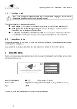
2.4
Modifications and transformations
Any modification or transformation of the barriers or the complete installation may result in unforeseen
risks.
Before any operation of this type, please contact the manufacturer.


