background image

13

4. Warning code/faultcodeandsolution

4.1 Warning code andsolution

When the "

"

symbolon the UPS LCDflashes,the UPS is in alarmstate. Press the pageturning

keyto the error state page(refer to 3.5), observe the alarm code andmakeappropriate
processingaccordingto the table below.
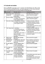
Alarm Indication

Possible reasons

Treatment measures

1

No battery
connection

1. No battery connected
2. Battery damaged

1. Checkthe connection of batteries.
2. Changethe batteries.

2

Battery low
voltage

Thebattery voltage is lessthan
the low voltage warningpoint.
The batteries dischargeto below
the alarm point.

After the battery has beensat for a
period of time, it canbe turned on
again. The built-in charger can be
turned on to chargethe battery.

4

Input neutral
and live cables
are reversed

1. Input neutral and live cables
are reversed.
2. Input groundcable is not
connected.
3. Output groundcable is not
connected.

1. Reverse the neutral andthe live
cables.
2. Check the ground cable
connection.

8

Battery over
voltage

UPS detects highbattery voltage

Checkthat the battery quantity
setting isconsistent with the actual
battery quantity.

9

Chargerfailure Abnormal charger hardware

Contact the supplier.

10

Over
temperature
alarm

1. Fan fault
2. Air ductof UPS rear panel is
blocked.
3. Overload
4. NTCsensor abnormal or
connection abnormal
5. Power componentIGBT is
damaged.

1. Checkthe rectifier fan.
2. Remove blockageson the rear
panelof the UPS.
3. Checkthe load.
4. If the above treatments do not
work, contact the supplier.

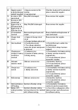
12

Fan fault

1. Fan wiring is loose.
2. Fan hardware abnormal

Checkthe fan and connection

13

ACfuse open Fuse blown

Contact the supplier.

14

EEPROM fault EEPROM chipdamages.

Contact the supplier.

21

Overload

The loadsexceedthe rated
power.

Checkthe load.

22

3times
consecutive
overload locks

3times consecutive overload
locks

Shut downandrestart UPS.

23

EPO action

Press EPO button.

1. Release EPO button.
2. Checkthe wiring harness on EPO
button.

24

Maintenance
switch action

The maintenance switch is
pressed.

Release maintenance switch.

Summary of Contents for DRAGON POWER 1-L

Page 1: ...DRAGON POWER 1 L 1 KVA 3 KVA USER MANUAL...

Page 2: ...atches ringsor similar metal objects B Use insulatedtools C Wear rubbershoesandgloves D Donot place metal tools or similarparts on the battery E Disconnectthe load fromthe batteries before removingthe...

Page 3: ...play 6 3 2Functionof button 7 3 3UPS workingstatustable of LCDdisplay 8 3 4Parameter query 9 3 5Functionsetting 10 4 Warningcode faultcodeandsolution 13 4 1Warningcodeandsolution 13 4 2Fault codeandso...

Page 4: ...s It continuously adjusts and filters the input voltage When the power supply is interrupted itwill providethe backuppowerfromthe backupbattery without timeinterruption In case of overload or inverter...

Page 5: ...uterinterface Smart slot optional Externalbattery connection USB Input over currentprotection ACINPUT Outputsocket EPO Battery interface Battery breaker optional Maintenance bypassswitch optional Outp...

Page 6: ...e sine wave Overload time Linemode 10min 102 110 load 1min 110 130 load 10s 130 150 load Battery mode 1min 102 110 load 10s 110 130 load 30s 130 150 load Efficiency Line Mode 94 Battery Mode 93 ECOMod...

Page 7: ...nly inanambient temperature range of0 40 32 104 Install it in a clean environment free from moisture flammableliquids gasesand corrosivesubstance ThisUPS containsnouser serviceablepartsexcepttheintern...

Page 8: ...statusmonitoring connectthe communicationcable one end to the USB RS232port and the other to the communicationport of your PC With the monitoring software installed you can schedule UPS shutdown start...

Page 9: ...ation Thebattery capacity 0 25 26 50 51 75 76 100 isdisplayed separately andthe battery iconflasheswhen the battery is low or not connected Other information AC Battery Bypass Inverter Outputworking F...

Page 10: ...eckingand mute function Testing in ACMode pressthe two buttons at the same time for 2secondsabove to test the battery Mute in Battery Mode Alarm TestingMode presstwo buttons at the sametime for 2 seco...

Page 11: ...on When the ACinput isout of limited rangeor shutoff the UPS will turn to Battery Mode Thebatteries supplythe inverter and have beepevery 4seconds BypassMode LCDdisplaycontent Instruction When theACin...

Page 12: ...larm information by default When UPS keepsnormal working the homepagedefault display will show the output voltage and frequency information Press right button more than 2sec LCDwill turn to the pollin...

Page 13: ...onfirmation button 0 5 2sec thenfinish the OPUsetting Thenumberbyleft sideofOPUwill keeplightingon no flashing 4 Press functional setting button over 2 sec quit the settingpageandbacktothe homepage Or...

Page 14: ...load 50 02 3 EconomicOperation Mode LCDDisplay Setting ECOisOFF bydefault canbe set as ONto improve the efficiency ofsystemoperation Note For the modelswith PF 1 OFFbydefault andunableto set 02 4 Eme...

Page 15: ...argerCurrent CHG LCDDisplay Setting When EP is set to ON the CHGoption appearson the functional settingpage the chargingcurrent canbeset 1 12Aoptional default 1A Noted if UPS built inbatteries the cha...

Page 16: ...utral andthe live cables 2 Checkthe groundcable connection 8 Battery over voltage UPS detects highbattery voltage Checkthat the battery quantity setting isconsistentwith the actual battery quantity 9...

Page 17: ...nel of the UPS is blocked 3 Overload 4 NTCsensorabnormality or abnormalwiring 5 Power componentIGBT is damaged 1 Please checkthe rectifier fan 2 Clean the obstacles onthe air ductof the rear panelof t...

Page 18: ...fthe voltagehasbeen reduced 67 Chargingover voltageor battery connection reversed 1 Hardware error 2 Number of battery wrong 3 Wiring wrong 1 Checkwhether the battery wiring or battery number meetsthe...

Page 19: ...oad Remove all loadsand restart the machine 5 With city electricity butno city electricity indication Mains voltage or frequencyover UPS inputrange Useamulti metertocheck whether the input voltageand...

Page 20: ...9 PhoenixDescription UPS fault 1 9 Openfromcommonconnection UPS isabnormal Closed UPS is normal General 2 7 Openfromcommonconnection UPS iswarning Closed UPS is normal GND 3 2 Internal GND usedtoconne...

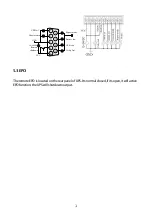
Page 21: ...4 5 9 8 7 Battery low UPS is on Utility fail UPS fail General alarm Remote shutdown GND VCC 5 3EPO Theremote EPO islocated onthe rear panel of UPS Its normal closed if its open it will active EPO func...

Page 22: ...time shouldnotbeless than12hours In normalcircumstances service life of the battery is 3 5years if the battery isfoundto be in poor condition it must bereplaced in advance When replacingthe battery it...

Page 23: ...www lbspower com Espa ol English...

Reviews: