15
4. Warning code/fault code and solution
4.1 Warning code and solution
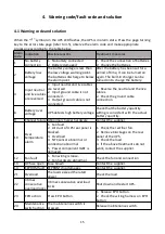
When the "
"
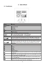
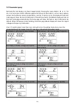
symbol on the UPS LCD flashes, the UPS is in alarm state. Press the page turning
key to the error state page (refer to 3.5), observe the alarm code and make appropriate
processing according to the table below.
Alarm
code
Indication
Possible reasons
Treatment measures
1
No battery
connection
1. No battery connected
2. Battery damaged
1. Check the connection of batteries.
2. Change the batteries.
2
Battery low
voltage
The battery voltage is less than
the low voltage warning point.
The batteries discharge to below
the alarm point.
After the battery has been sat for a
period of time, it can be turned on
again. The built-in charger can be
turned on to charge the battery.
4
Input neutral
and live cables
are reversed
1. Input neutral and live cables
are reversed.
2. Input ground cable is not
connected.
3. Output ground cable is not
connected.
1. Reverse the neutral and the live
cables.
2. Check the ground cable
connection.
8
Battery over
voltage
UPS detects high battery voltage
Check that the battery quantity
setting is consistent with the actual
battery quantity.
9
Charger failure Abnormal charger hardware
Contact the supplier.
10
Over
temperature
alarm
1. Fan fault
2. Air duct of UPS rear panel is
blocked.
3. Overload
4. NTC sensor abnormal or
connection abnormal
5. Power component IGBT is
damaged.
1. Check the rectifier fan.
2. Remove blockages on the rear
panel of the UPS.
3. Check the load.
4. If the above treatments do not
work, contact the supplier.
12
Fan fault
1. Fan wiring is loose.
2. Fan hardware abnormal
Check the fan and connection
13
AC fuse open
Fuse blown
Contact the supplier.
14
EEPROM fault EEPROM chip damages.
Contact the supplier.
21
Overload
The loads exceed the rated
power.
Check the load.
22
3 times
consecutive
overload locks
3 times consecutive overload
locks
Shut down and restart UPS.
23
EPO action
Press EPO button.
1. Release EPO button.
2. Check the wiring harness on EPO
button.
24
Maintenance
switch action
The maintenance switch is
pressed.
Release maintenance switch.
Summary of Contents for Dragon Power 2
Page 1: ...USER MANUAL ...


