background image

3Installation

User Manual

22

www.lbspower.com

Install combination units

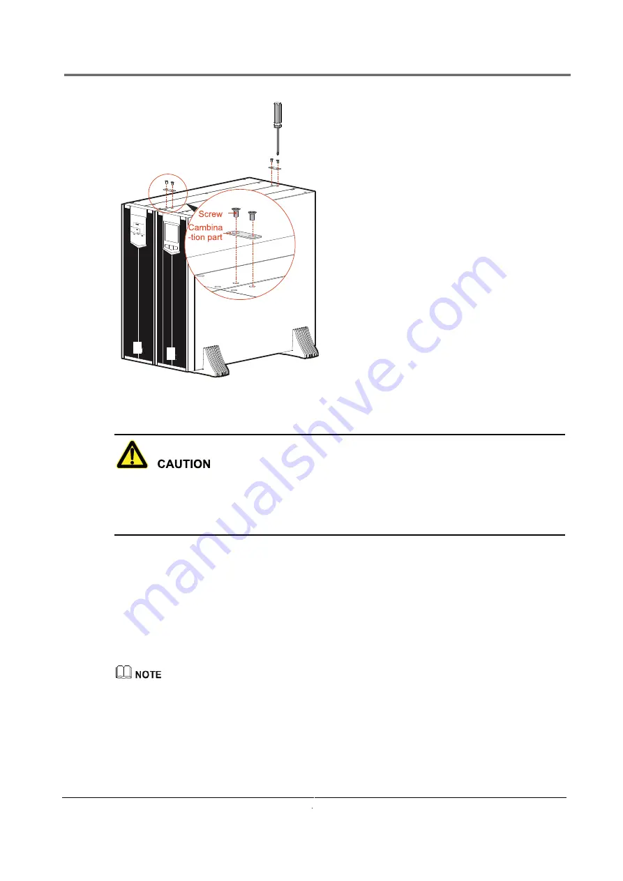
Every two adjacent devices need to be connected by two combination parts at the top of the device,

that is to say, add one optional (distribution module or battery box), it needs to install another 2

combination parts.

----End

3.3.2 Rack-mounting

10-40kVA series UPS and the optional also can be installed in 19 inch standard cabinet to use.

The rack-mounting procedure of UPS, battery box and distribution module is the same, in this section,
we take the UPS installation as an example to illustrate.

Fasten the two angle irons onto the two sides of the UPS by 4 sunk screwsM4×8, as shown in

2032624074.26.264318872 . .

Summary of Contents for DRAGON POWER 3

Page 1: ...DRAGON POWER 3 15 KVA 60 KVA USER MANUAL ...

Page 2: ...care electric shock prompting Provides a tip that may help you solve a problem Summaries Thank you for choosing the Uninterruptible Power System hereinafter referred to as the UPS product This document gives a description of the 10 40kVA series UPS including the features performance appearance structure working principles installation operation and maintenance etc Please save the manual after read...

Page 3: ...Provides additional information to emphasize or supplement important points in the main text Product standard Q ZZKJ 007 Change History Changes between document issues are cumulative The latest document issue contains all the changes made in earlier issues ...

Page 4: ...irements 3 1 3Environment Requirements 3 2 Overview 5 2 1 Product Intro 5 2 1 1Model Meaning 5 2 1 2 Features 5 2 1 3 Appearance 6 2 1 4 Ilustrations 9 2 2 Work Principle 10 2 2 1 Work Principle Diagram 10 2 3 Work Mode 10 2 3 1 Optionals 11 2 3 2 Distribution Module 14 2 3 3 Battery Box 16 3 Installation 17 3 1 Unpacking Checking 17 3 2 Installation 17 3 2 1 Select Input Breaker 18 ...

Page 5: ...re Startup 33 4 2 Startup Operation 33 4 3 Shutdown Operation 33 4 4 Parallel System Operation 34 4 4 1 Start Parallel System 34 4 4 2 Shut Down Parallel System 35 4 4 3 Exit Paralle Systm Online 35 4 4 4 Add New UPS into Parallel System Online 35 4 4 5 Redundance Funcion of Parallel System 36 4 5 Periodic Preventive Maintenance 36 4 6 Battery Maintenance 36 4 7 UPS Setting 37 4 8 Troubleshooting ...

Page 6: ...www lbspower com A Technical Specifications 49 B Acronyms and Abbreviations 52 ...

Page 7: ......

Page 8: ...fore operating please read the announcements and operation instructions in this section carefully to avoid accident The DANGER WARNING CAUTION etc in the manual are not all the safety announcements that you must abide by they are just the supplements for the safety announcements during operating Our Company does not undertake the responsibility caused by violating common safety operation requireme...

Page 9: ...d gloves and use tools with insulated handle Don t put tools or other conductive objects on the battery It is prohibited to short the positive pole and negative pole of the battery or connect them reversely which is to avoid fire or electric shock Before connecting or disconnecting the battery terminals disconnect charger first The battery must be with the same type model and manufacturer Battery ...

Page 10: ... connection such asAC power battery power etc toisolate power input Do not do anywork on theUPS until it is powered off completely 10min Otherwise the output may exist electricity which may cause electric shock When dismantling fan do not put fingers or tools into the rotating fan to avoid device damage or human injury 1 3 Environment Requirements Do not put the UPS in the environment where has in...

Page 11: ... clearance between the rear or the side ofUPS and adjacent devices or wall should be at least 300mm 500mm Poor ventilation will rise temperature inside UPS which will reduce the service life of inner components and even affect the life span of the UPS The UPS must be used below2000m If the altitude exceeds2000m it needs to decrease the rated power according to GB3859 2 93 to use ...

Page 12: ...3 mode three phase input single phase output three in one out is 31 mode single phase input single phase output one in one out is 11 mode 2 1 2 Features Completely digitalized smart control The UPS support various input and output mode such as 33 mode 31 mode 11 mode The UPS can monitor the grid frequency 50Hz 60Hz and self adapt the frequency The output voltage can be set to 208V 220V 230V 240V w...

Page 13: ...y Low mains input voltage Adopt the independent rapid detection technology When output load is small even the battery voltage is 80V which is the main slow limit the battery still doesn t discharge Therefore in the mains mode all output power gets from the grid which is to ensure the battery in 100 energy storage status and at the same time reduce the battery discharge times and prolong the servic...

Page 14: ...t information etc circularly Long press button for 5s the LCD will enter setting page Short press to select the setting command long press button to confirm the command OFF button When UPS is on long press button for 1s the UPS will be shut down ON button When UPS off long press button for 1s the UPS will be started When UPS on at mains mode long press button for 3s the UPS begin to perform batter...

Page 15: ... capacity UPS fault indication and buzzer mute etc Work mode display area Shows the work status of UPS mains inverter bypass power supply battery inverter ECO Fault type and corresponding dispose please see4 8 Troubleshooting Rear panel Structure of rear panel Detail of the wiring terminal of each mode please see3 4 1 Wiring of UPS Only when the bypass maintain detection BMD and EPO port are all s...

Page 16: ...unction won t be used please short the port by equipped 4P terminal When the function needs to be used dismantle the short wire of BMD or EPO port and connect it with corresponding status signal input of maintenance bypass breaker or EPO 2 1 4 Fittings Illustration 10 40kVA series UPS and distribution module has 4 kinds of copper bar as shown in2032624074 0 264318872 User can set the UPS to 33 mod...

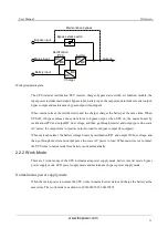
Page 17: ... lbspower com Copper bar installation position of 33 mode UPS Copper bar installation position of 31 mode UPS 2 2 Work Principle 2 2 1 Work Principle Diagram Work principle diagram of the UPS is as shown in 2032624074 26 264318872 ...

Page 18: ...ins boosts by rectification PFC and output DC bus voltage and then go through inverter and output pure sine wave AC power the output turns to inverter output to load from bypass output if equipped When mains abnormal the battery voltage boosts by rectification PFC and output DC bus voltage and then go through inverter and output pure sine wave AC power to load When mains recover normal the UPS tur...

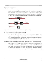
Page 19: ...top discharging if the mains recover normal the rectifier will transfer to mains input automatically and charge the battery at the same time That is to say the UPS recover normal mains power supply mode If the mains always abnormal and the battery is running up the UPS will send sound and light alarm and stop working till battery low voltage point At that time the buzzer long beeps to alarm the po...

Page 20: ...ply mode just suitable for single UPS At the ECO mode when bypass voltage normal the power for load is prior supplied by bypass when bypass voltage abnormal the power for load turns to inverter ECO mode is an economic operation mode For the load which does not require high quality user can select ECO mode to reduce the energy consumption At the ECO mode the UPS efficiency can be 99 Maintenance byp...

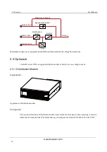
Page 21: ... solid line stands for the energy flow direction 2 3 Optionals 10 40kVA series UPS can equip distribution module or battery box according to needs 2 3 1 Distribution Module Appearance Appearance of distribution module Front panel The operation breakers of distribution module locate inside the front panel when operating it needs to dismantle the front panel fist The dismantle way of frontpanel as s...

Page 22: ...r then close the maintenance bypass breaker turn off the AC input breaker bypass breaker and AC output breaker at this time the power for load turns to maintenance bypass the input and output of the UPS is disconnected the maintenance can be done Recover inverter power supply from maintenance bypass power supply connect the wires of UPS and distribution module including bypass maintain detection s...

Page 23: ...2Overview User Manual 16 www lbspower com Rear panel Rear panel of distribution module 2 3 2 Battery Box Appearance Appearance of battery box Rear panel Rear panel of battery box ...

Page 24: ...e selecting for AC input and output wire DC input wire and corresponding breakers needs to be judged by the UPS max steady state phase current 2032624074 26 264318872 shows the max steady state phase current of each work mode 2032624074 26 264318872 shows the rated current of recommended breakers 2032624074 26 264318872 shows the min recommended wire cross sectional area Select the wires and break...

Page 25: ...5 1P 125 1P DC input A 50 3P 50 3P 50 3P 63 3P 63 3P 63 3P 80 3P 80 3P 80 3P AC output A 32 3P 63 1P 63 1P 50 3P 100 1P 100 1P 63 3P 125 1P 125 1P 3 2 2 Select Wires For the wire cross sectional area of AC input output and battery please see the recommended value in 2032624074 26 264318872 2032624074 26 264318872 and choose upwards When the UPS set to 31 mode or 11 mode we provide three phase shor...

Page 26: ... 16 1 16 1 DC input BATN 6 3 6 3 6 3 10 3 10 3 10 3 10 3 10 3 10 3 Grounding wire PE 6 1 6 1 6 1 10 1 10 1 10 1 10 1 10 1 10 1 Contrast list between wires and wiring terminals Wire cross sectional area unit mm2 Wiring terminal type 4 RV3 5 6 6 RV5 5 6 10 RNBS8 6 16 RNBS14 6 25 RNBS22 6 The equipped wires by our company are all passed the national standard or UL certification the quality is perfect...

Page 27: ...ogether as shownin2032624074 26 264318872 Assemble support base Put the UPS onto the assembled support base as shown in 2032624074 26 264318872 Install the UPS End Install the UPS with battery box optional or distribution module When equip battery box or distribution module the installation procedure is the same in this section we take the installation of one UPS and one distribution module as an ...

Page 28: ...d to add the assemble way is the same Put the UPS and distribution module onto the assembled support base as shown in2032624074 26 264318872 Install the UPS and distribution module Take out the combination parts and screws and fasten them onto the top of the UPS and distribution module as shown in 2032624074 26 264318872 ...

Page 29: ...x it needs to install another 2 combination parts End 3 3 2 Rack mounting 10 40kVA series UPS and the optional also can be installed in 19 inch standard cabinet to use The rack mounting procedure of UPS battery box and distribution module is the same in this section we take the UPS installation as an example to illustrate Fasten the two angle irons onto the two sides of the UPS by 4 sunk screwsM4 ...

Page 30: ...front panel can be dismantled front during transporting do not make it bear any strength The device needs to be transported by two or more people Push the UPS into the cabinet and fasten it by screws as shown in 3 4 Fasten the UPS The battery box is heavy when installing the battery box must be installed from bottom and down below the UPS End ...

Page 31: ...wer wire at the place where is easy to be trod or tripped Before wiring the wires of 10 20kVA series UPS distribution module optional should across the wiring protection cover the installation of wiring cover please see section 3 4 1 Install wiring covers and then connect them to corresponding wiring terminals 3 4 1 Wiring of UPS 33 mode The input and output wiring of 33mode is as shown in 2032624...

Page 32: ...UPS as shown in2032624074 26 264318872 The wiring diagram of 31 mode is as shown in 2032624074 26 264318872 Wiring diagram of 31 mode 3 4 2 Wiring Between UPS and Battery Box The wiring of parallel connected battery box and each mode UPS is the same in this section we take 20 25kVA 33 mode as an example to illustrate ...

Page 33: ...lel connected battery boxes Wiring diagram between UPS and several parallel connected battery boxes The wiring between UPS and parallel connected battery boxes must be connected strictly according to 2032624074 26 264318872 2032624074 26 264318872 avoid wrong connection or short circuit ...

Page 34: ... neutral wire 2032624074 26 264318872 shows the other wiring way there are 16 cells separately in two independent batter cabinet every battery cabinet has one 2P breaker the external wiring includes BAT BAT No matter which wiring way the BAT BAT inside the UPS has been shorted The selection of battery wires and breaker specification please see 2032624074 26 264318872 2032624074 26 264318872 NO 1 B...

Page 35: ...n2032624074 26 264318872 1 the model of copper bar please see2 1 4 Fittings Illustration Wiring diagram of 33 mode UPS and distribution module 31 mode Dismantle the copper bar 1 and 2 as shown in 2032624074 0 264318872 and take out the copper bar 1 and 4 from the package of distribution module install them to the distribution module as shown in2032624074 26 264318872 1 and 4 the model of copper ba...

Page 36: ...ection we take 20 25kVA 33 mode as an example to illustrate Take out the protection cover and fasten one type L protection cover to the back of the UPS by 2 pieces of flat head screw M4 as shown in2032624074 0 264318872 Install type L protection cover 1 Insert the other type L protection cover into the installed one and fasten it by 2 pieces of flat head screw M4 as shown in2032624074 26 264318872...

Page 37: ...in parallel system on the basis of 2032624074 0 264318872 2032624074 26 264318872 UPS1 UPS2 Output neutral wire Grounding wire Input live wire U Input live wire V Input live wire W Input neutral wire Battery Battery neutral wire Battery Breaker 5 Breaker 6 Breaker 7 Breaker 8 Bypass input U Bypass inputV Bypass inputW Breaker 1 Output live wire U Output live wire V Output live wire W Breaker 2 Bre...

Page 38: ... live wire V Input live wire W Input neutral wire Battery Battery neutral wire Battery Breaker 1 Breaker 2 Breaker 3 Breaker 4 Breaker 5 Breaker 6 Breaker 7 Breaker 8 Wiring diagram of 31 mode parallel system Connect the parallel port of each unit in parallel by parallel wires as shown in 2032624074 26 264318872 Wiring diagram of parallel wire ...

Page 39: ...e phase The parallel system of this series UPS can share battery groups but the battery amount of each UPS must be the same Connect the parallel ports of each unit in parallel by equipped shielding communication wire The two RJ45 parallel ports are the same they are redundancies and backup for each other to increase the reliability of the system once one ofthem isnot connected the UPS will sendala...

Page 40: ...ce check if the wiring of the RS485 port is correct If it is long backup model check if the wiring between UPS and battery box is correct and reliable Check if the wiring is neat and the wire binding is in accordance with the specification Check if the installation and wiring are good for transformation expansion and maintenance in future Check that there is no short circuit in the output of the U...

Page 41: ...stem according to the 4 2 Startup Operation one by one After each unit in parallel system outputs by inverter measure the inverter voltage of each paralleled unit The voltage difference between max and min voltage should be within 8V Close the breaker of paralleled unit in parallel distribution cabinet measure the circulating current of parallel unit and the current should be less than 3A When the...

Page 42: ...ieve online hot maintenance or replacement Switch off breaker in the distribution box which connects with the faulty UPS Close the fault UPS according to shutdown procedures Exit parallel system online When the parallel system works normally it s better not to exit the output from parallel system before the unit closed or the power system will be abnormal 4 4 4 Add New UPS into Parallel System Onl...

Page 43: ...nnected Check the working status of cooling fans regularly Prevent sundries from blocking the air outlet If damaged please replace it in time Check the battery voltage and the working status of UPS regularly 4 6 Battery Maintenance The working life of battery is based on the environment temperature and discharge times Using battery in the high temperature for a long time or discharging battery dee...

Page 44: ...e mode and it needs to set to parallel mode enter this setting page the PRL flickers If you confirm to select the setting press ON button more than 1s exit the setting page the setting succeeds If you do not confirm to select the setting 20s later it will exit the setting page automatically Corresponding LCD display is as shown in 2032624074 26 264318872 PRL mode SGL single mode SGL setting page w...

Page 45: ... If you confirm to select the setting press ON button more than 1s exit the setting page the setting succeeds If you do not confirm to select the setting 20s later it will exit the setting page automatically CorrespondingLCD display is as shown in2032624074 26 264318872 ECO mode INV prior mode INV prior setting page when the UPS has been set to ECO prior mode and it needs to set to in INV prior mo...

Page 46: ...omatically Corresponding LCD display is as shown in2032624074 26 264318872 Inverter voltage 208V setting The setting of 220V 230V 240V inverter voltage is the same Input and output mode setting Input and output mode setting page in the setting page P N I O 3 1 flickers If you confirm to select the setting press ON button more than 1s exit the setting page the setting succeeds If you do not confirm...

Page 47: ...not confirm to select the setting 20s later it will exit the setting page automatically Corresponding LCD display is as shown in2032624074 26 264318872 Time setting Year month day setting page in the page press ON button more than 1s it will enter year month day setting page In the setting page the 6 numbers all can be set Corresponding setting place flickers Press ON button or OFF button more tha...

Page 48: ... If you confirm the setting press ON button more than 1s exit the setting page the setting succeeds If you do not confirm the setting 20s later it will exit the setting page automatically Corresponding LCD display is as shown in2032624074 26 264318872 Time setting confirm Rack display setting Rack mounting setting page when the UPS has been set to tower display mode and it needs to set to rack dis...

Page 49: ...ng LCD display is as shown in2032624074 26 264318872 Tower setting 4 8 Troubleshooting 4 8 1 Common Fault As shown in 2032624074 26 264318872 it only includes some common fault diagnosis If any doubt contact the local office or distributor for details Troubleshooting Fault phenomenon Possible reason The mains normal after starting the UPS it outputs normally but it works in the battery mode and th...

Page 50: ...r ones successively Buzzer long beeps fault indicator lights on UPS works in bypass mode and inverter failure 1 The output is overload The load is too heavy and beyond the rated power of the UPS Please reduce load or select a UPS with larger power capacity If it is temporary bypass caused by impact of load start and recovers automatically it still is normal 2 UPS over temperature protection Check ...

Page 51: ... abnormal Please check if the phase sequence of mains wiring is normal BMD Long beep UPS maintenance bypass fault the inverter output is closed Please check the detection port of maintenance bypass on rear plate is short circuit BUS Long beep The inner busbar voltage fault the inverter output is closed TMP Long beep UPS is over temperature protected the inverter output is closed Please check if co...

Page 52: ...ery 2 0s The charging fuse fault please check is the fuse on charging board is invalid BYP Slow beep alarm once about every 2 0s At mains status the bypass voltage abnormal frequency abnormal phase sequence abnormal or mode setting mismatches the wiring Please check if the bypass breaker is closed if the bypass phase sequence is normal if the wiring way of bypass matches the system mode setting CA...

Page 53: ...blocked fan damage etc UPS output fault including output overload protection output short circuit etc UPS battery fault including battery over voltage under voltage protection etc UPS parameter mismatching fault UPS parallel wire fault UPS inner power fault charger fault charging over temperature charging short circuit or charging fuse fault bypass fault parallel communication abnormal inner commu...

Page 54: ... Parallel parameters inconformity Parameter PRL Parallel wire fault Parallel PWR UPS work power fault Power CHG UPS charger fault Charge BYP UPS bypass abnormal Bypass CAN CAN communication of parallel system abnormal CAN SCI Inner communication abnormal SCI INV Inverter fault Inverter The above table is just for user to know about the meaning of abnormal alarm prompting If it may be inner compone...

Page 55: ... explosive corrosive object is not allowed to shipping with the device While midway transportation do not put the device in the open air The device cannot suffer any rain snow or liquid material or mechanical damage 5 3 Storage During storing place the UPS according to the marked direction The package box should be far away from ground for 200mm and keep at least 500mm from wall eat source cold so...

Page 56: ...ge Hz 50 60 10 Hz Bypass input voltage range V 220 230 240 20 phase voltage default is 220 Input power factor 0 99 Input THDI Resistive full load 3 non linear full load 5 Battery voltage VDC 144 240 can be selectedfrom 12 cells 20 cells default is 16 cells when the battery voltage is set from 12 cells 15 cells the output of the UPS decreases to 75 rated 12V battery Charge current A 1 10A settable ...

Page 57: ... output long time Transfer time of bypass and inverter ms Synchronization 1ms asynchronization 10ms System efficiency Up to 96 Overload capacity 115 no protection 115 130 15min 130 150 1min 150 200ms Others DC startup function Equipped Panel display LCD shows the running status of the UPS Communication port RS485 Alarm function Alarm for battery low voltage mains abnormal UPS fault output overload...

Page 58: ...nual 6Technical Specifications 51 www lbspower com Model Index 10kVA 33 mode 15kVA 33 mode 20 25kVA 33 mode Size W D H mm3 438 500 130 3U Weight kg 20 Specifications are subject to change without prior notice ...

Page 59: ...ual 52 www lbspower com 7 Acronyms and Abbreviations A AC Alternating Current B BMD Bypass Maintain Detection D DC Direct Current E ECO Economic Operation Model EPO Emergency Power Off L LCD Liquid Crystal Display P PE Protective Earthing ...

Page 60: ...User Manual 7Acronyms and Abbreviations 53 www lbspower com R RS485 Recommend Standard485 S SNMP Simple Network Management Protocol U UPS Uninterruptible Power System ...

Page 61: ...www lbspower com Español English ...

Page 62: ......

Reviews: