-4-
UDOS 51E
–
Operator’s
Manual v1.6
To reduce the risk of injury, it is
recommended to unplug the
tool before changing modes.
1)
Position the tool with the pad facing down resting on
a surface.
2)
Rotate the hub to align one of the two lines to the
white line on the tool body
3)
If going from a DA setting to Rotary, align any one of
the white Stall-Aware® markings on the backing plate
to the aligned lines in Step 2.
4)
Push the adjustment collar down and rotate into the
desired mode.
5)
Release the adjustment collar allowing it to move
upward. Note: Ensure the lock indicator ring is NOT
visible.
UDOS MODE SETTINGS
Adjustment Collar Position
R
S
P1
P2
P3
Rotary
Sand
(8mm DA)
12mm
DA
15mm
DA
21mm
DA
The tool is equipped with load sensing. If an overload
condition occurs, the motor will stop pausing for about 1-
2 seconds, then try to restart. If after 6 restarts the
overload condition still exists, the motor will shut down.
Release the trigger, and allow the tool to cool for 3
minutes before continuing.
The rotational speed of the tool is adjusted using the
scroll thumb wheel on top of the handle. The following
table provides the approximate spindle RPM for each
setting of the thumb wheel.
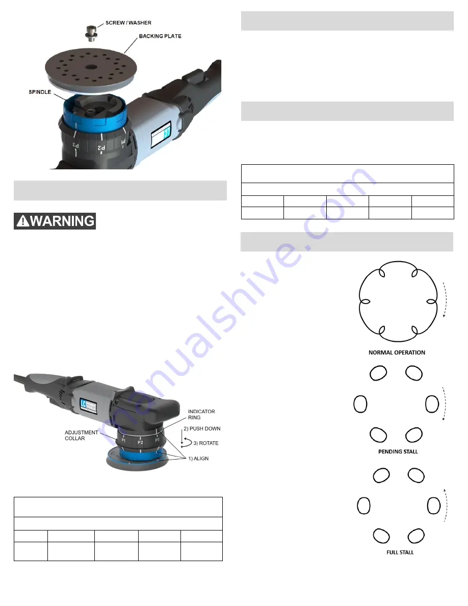
The 6 white Stall-Aware®
marks on the top of the
UDOS
backing
plate
provide
a
convenient
indication of the orbital
rotation of the pad. During
normal
operation
the
Stall-Aware® markings will
rotate
clockwise
and
appear similar to the
pattern shown.
Applying more pressure
will cause the pattern to
shift to a series of clockwise
rotating circles as shown,
indicating a
pending stall
.
If excessive downward
pressure is applied, the
circle pattern will appear to
stop then rotate counter
clockwise, indicating a
full
stall
. Decrease the pressure
on the tool to restore proper
orbital action.
APPROXIMATE ORBIT SPEED (Orbits/minute)
Thumb Wheel Setting
1
2
3
4
5
1000
1350
1700
2050
2400
MODE SELECTION
OVERLOAD PROTECTION
SPEED ADJUSTMENT
STALL-AWARE
®


