Rev: 07.12.18
Page 5
CCD-0001607
2.
Separate the motor assembly from the top drive block, so that the spur gears move freely.
3.
Place 2 of the appropriate gear rack assemblies, an upper and lower, on the matching column.
Note:
The 2 gear rack pieces with LCI SlimRack® stickers (Fig. 7) are intended for the lower portions of the
SlimRack® columns, or furthest away from the SlimRack® motors.
Note:
Failure to uniformly install the upper (Fig. 9) and lower (Fig. 10) gear racks will cause the SlimRack®
System to be “out of time," and will cause the system to malfunction.
4.
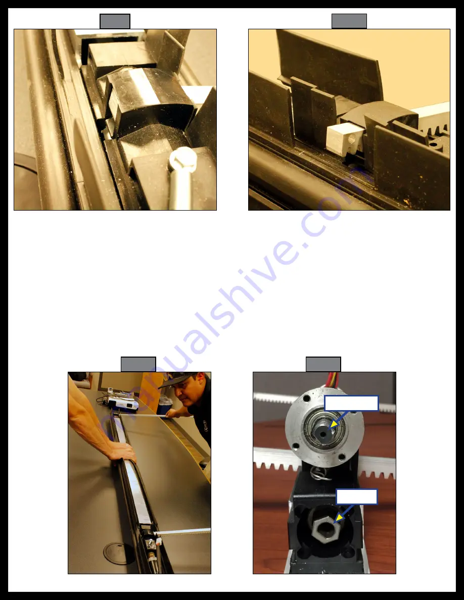
Insert both the upper and lower gear rack pieces uniformly (Fig. 11), through the primary wipe seal and
then the secondary wipe seal, allowing the gear racks to feed into the spur gears at the same time.
Note:
The timing and synchronization of the gear racks
MUSt
be maintained.
5.
Insert gear racks through the spur gear until the installed end bracket rests on the spur gear housing.
This ensures the timing is correct before motor assembly.
Fig. 11
Fig. 12
Fig. 10
Fig. 9
Drive Shaft
Coupler


