User manual
Page 2/4
LD DIDACTIC GMBH
.
Leyboldstrasse 1
.
D-50354 Huerth
.
Phone +49 2233 604-0
.
web: www.ld-didactic.com
.
e-mail: info@ld-didactic.de
by LD Didactic GmbH
Printed in the Federal Republic of Germany
Technical alterations reserved
3
Technical data
Supply voltage:
U = 12 V=
differential pressure indicator
Supply voltage:
U = 5 V=
Interface:
SENT (3 µs) acc. to SAE J2716
Pressure range:
0-125 kPa
SENT channels:
FDC with pause, slow channel
SENT signals:
1*12 bit, single secure
Accelerator position transducer
Supply voltage:
U = 12 V=
Interface, pedal sensor:
SENT (3 µs) acc. to SAE J2716
Sensitivity:
3 mT
SENT channels:
FDC without pause, slow ch.
SENT signals:
1*12 bit
Neutral gear position transducer
Interface:
PWM
Supply voltage:
U = 5 V=
Low level:
U
L
< 1 V
High level:
U
H
> 4 V
Frequency:
f
d
= 125 Hz
Pull-up resistor
R = 1 k
Ω
Brake light/pedal switch
Interface, brake pedal:
Digital
Interface, brake light:
Digital
High level:
U
H
= 12 V
Knock sensor amplifier
Input filter:
f
g
= 1.6 kHz
High level:
U
H
= 7 V
Pulse width:
t
kn
= 400 ms
4
Setup and Functional Checks
Connect the device to the power supply at Terminals
15 and 30
(1)
and the ground
(7)
.
Insert the 4-mm safety bridging plugs into the socket
(3)
above the control unit as well as in all socket pairs
below the control unit.
Insert a bridging plug into position
2
to activate the
CAN terminating resistor.
Turn on the supply voltage and the ignition.
5
Functional description
Differential Pressure Indicator (8)
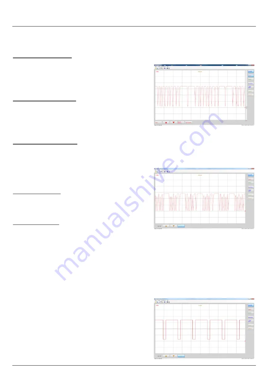
Based on the measured differential pressure be-
tween Filter Outlet (P1) and Filter Inlet (P2), the
pressure sensor determines the actual exhaust
flow through the diesel particulate filter and thus
the degree of clogging of the filter. This value is
transmitted via a SENT interface to the engine
control unit. If the determined value exceeds a
limit stored in the control unit, a regeneration pro-
cess is initiated to burn the residues present in the
particulate filter.
Accelerator Pedal Position Indicator (9)
The detection of the accelerator pedal position
takes place with a Hall-effect linear sensor, type
HAL283 with a SENT interface. Thus, voltage is
generated proportional to the magnetic flux
through the Hall element.
Indicator for Neutral Position of Transmission (10)
This is an active distance sensor based on the Hall
effect with a PWM interface. The sensor reacts to
magnetic field changes by changing the Hall volt-
age. Under the influence of a magnetic field or a
ferromagnetic material, the sensor generates a
pulse width modulated signal, in whose duty cycle
the distance as well as the polarity of the magnetic
field is coded. A small depression on the magnet
holder marks the north pole.


