


Page 3/4
User manual
Brake Light / Brake Pedal Switch (11)
Contactless, combination brake light / brake pedal
switch based on the Hall effect, which generates
a digital signal for the actuation of the brake light,
and a corresponding inverted signal for analyzing
the brake pedal position. The sensor is sensitive
to polarity.
Optional: Knocking Sensor (12)
The signal from the knocking sensor is filtered in
order to suppress electrical noise. The sensitivity
can be adjusted at Potentiometer
6
, for which a
knocking signal is detected. This is then visually
displayed and outputted as a pulse of approx.
400 ms in width and 7 V in amplitude at 4-mm out-
put.
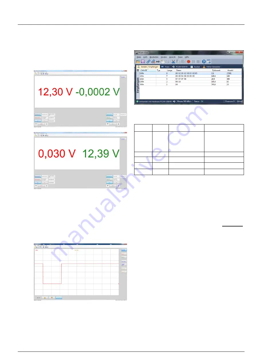
CAN bus
Differential pressure sensor G505:
The sensor signals are mirrored internally on the CAN bus.
The following signals are sent:
CAN-ID
Length
Position
Signal
100
8
Bytes 2-4, all bits
(byte 2 = nibble 0,
byte 3 = nibble 1,
byte 4 = nibble 2)
Differential pressure
Conversion:
p = -(x-800)/3 [mbar]
where x = nibble 0 to
2)
101
7
Enhanced Message
102
4
Short Message
200
2
Byte 1, bits 0-15
Distance
300
1
Byte 1, bit 0
Brake light
Note:
Numbering system of bytes: 1 (left) to 8 (right)
Numbering system of bits:
0 (right) to 7 (left)
Example of converting the differential pressure:
CAN message
$100: 0D
06
09
0F
03 01 09 04
p
= -(69Fh – 800)/3 = -(1695-800)/3 =
-298 mbar


