background image

14

DEUTSCH

ENGLISH

MANUFACTURER´S DECLARATIONS

MANUFACTURER‘S WARRANTY & LIMITATIONS OF LIABILITY  

You can find our current warranty conditions and limitations of liability at: https://cdn-shop.adamhall.com/media/pdf/MANUFACTURERS-DECLARATIONS_

LD_SYSTEMS.pdf To request warranty service for a product, please contact Adam Hall GmbH, Adam-Hall-Str. 1, 

61267 Neu Anspach / Email: Info@adamhall.com / +49 (0)6081 / 9419-0.

CORRECT DISPOSAL OF THIS PRODUCT

(valid in the European Union and other European countries with a differentiated waste collection system) 

This symbol on the product, or on its documents indicates that the device may not be treated as household waste. This is to avoid environ-

mental damage or personal injury due to uncontrolled waste disposal. Please dispose of this product separately from other waste and have it 

recycled to promote sustainable economic activity. Household users should contact either the retailer where they purchased this product, or their 

local government office, for details on where and how they can recycle this item in an environmentally friendly manner. Business users should 

contact their supplier and check the terms and conditions of the purchase contract. This product should not be mixed with other commercial waste 

for disposal.

FOR INDOOR USE ONLY

This symbol indicates electrical equipment designed primarily for indoor use.

FCC STATEMENT

1.  This device complies with Part 15 of the FCC Rules. Operation is subject to the following two conditions:
 

(1) This device may not cause harmful interference, and


(2) This device must accept any interference received, including interference that may cause undesired operation

2.  any Changes or modifications not expressly approved by the party responsible for compliance could void the user‘s authority to operate the equipment.

NOTE: This equipment has been tested and found to comply with the limits for a Class B digital device, pursuant to Part 15 of the FCC Rules. These 

limits are designed to provide reasonable protection against harmful interference in a residential installation. 

This equipment generates uses and can radiate radio frequency energy and, if not installed and used in accordance with the instructions, may 

cause harmful interference to radio communications. However, there is no guarantee that interference will not occur in a particular installation. 

If this equipment does cause harmful interference to radio or television reception, which can be determined by turning the equipment off and on, 

the user is encouraged to try to correct the interference by one or more of the following measures:

Reorient or relocate the receiving antenna.

Increase the separation between the equipment and receiver.

Connect the equipment into an outlet on a circuit different from that to which the receiver is connected.

Consult the dealer or an experienced radio/TV technician for help.

FCC RADIATION EXPOSURE STATEMENT

This equipment complies with FCC radiation exposure limits set forth for an uncontrolled environment. This equipment should be installed and 

operated with minimum distance 20cm between the radiator & your body

CE COMPLIANCE

Adam Hall GmbH states that this product meets the following guidelines (where applicable):

R&TTE (1999/5/EC) or RED (2014/53/EU) from June 2017

Low voltage directive (2014/35/EU)

EMV directive (2014/30/EU)

RoHS (2011/65/EU)

The complete declaration of conformity can be found at www.adamhall.com. 

Furthermore, you may also direct your enquiry to info@adamhall.com.

EU DECLARATION OF CONFORMITY

Hereby, Adam Hall GmbH declares that this radio equipment type is in compliance with Directive 2014/53/EU. 

The full text of the EU declaration of conformity is available at the following 

internet address: 

www.adamhall.com/compliance/ 


Printing errors and mistakes, as well as technical or other changes are reserved!

Summary of Contents for IPA 412 T

Page 1: ...USER S MANUAL BEDIENUNGSANLEITUNG More languages online at ld systems com IPA 412 T 424 T INSTALLATION DSP POWER AMPLIFIER LDIPA412T LDIPA424T ...

Page 2: ...NTS 5 ASSIGNMENT OF THE TERMINAL BLOCK CONNECTIONS AND SETUP EXAMPLES 11 TECHNICAL DATA 11 MANUFACTURER S DECLARATIONS 14 DEUTSCH SICHERHEITSHINWEISE 15 EINFÜHRUNG 16 EIGENSCHAFTEN 16 LIEFERUMFANG 17 ANSCHLÜSSE BEDIEN UND ANZEIGEELEMENTE 17 BELEGUNG DER KLEMMBLOCKANSCHLÜSSE UND SETUP BEISPIELE 23 TECHNISCHE DATEN 24 HERSTELLERERKLÄRUNGEN 26 ...

Page 3: ... by the user which have not been expressly agreed upon with the party responsible for compliance could void the user s authority to operate the device FOR DEVICES CONNECTED TO A POWER SUPPLY 24 CAUTION If the device s power cable has a protective contact it must be connected to an outlet with a protective ground conductor Never deactivate the power cable s protective ground conductor 25 The mains ...

Page 4: ...mains at least for mains switches or their positions and all those cases where safety is involved WARNING HIGH VOLUME AUDIO PRODUCTS This device is intended for professional use The commercial operation of this device is subject to applicable national regulations and directives for accident prevention As the manufacturer Adam Hall is legally bound to specifically point out potential health risks H...

Page 5: ... expansion card with the same functionality as the Ethernet expansion card plus Dante connectivity Fault relays with terminal block connections per channel pair Universal wide range PFC switching power supply Temperature controlled active cooling with low noise fans in 2 zones PACKAGING CONTENT 1 x LD Systems IPA 424 T or IPA 412 T installation amplifier with pre assembled rack brackets 2 x 6 pole...

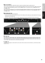
Page 6: ...is routed to speaker output CH2 The same also applies to channels 3 and 4 The corresponding level controls work independently of each other PAR Parallel Mode In parallel mode a signal present at line input IN1 is routed to speaker outputs CH1 and CH2 while line input IN2 is deactivated Level controls CH1 and CH2 are used to separately set the volume for the corresponding amplifier channel A signal...

Page 7: ...nd 3 4 The description of the preset and corresponding DIP switch positions can be found in the table below IMAGE DIP switch 3 DIP switch 4 DSP preset CH1 2 CH3 4 Use ON DIP OFF OFF All channels flat Full range speaker ON 1 2 3 4 DIP OFF ON High pass filter on all channels HPF 95Hz LR 24dB Satellite speaker ON DIP ON OFF CH1 CH2 High pass filter HPF 95Hz LR 24dB Satellite speaker CH3 CH4 Low pass ...

Page 8: ... the user manual of the additional remote bus accessories The DIP switch currently has no function DIP SWITCH 4 REM LOCK REMOTE LOCK Move DIP switch 4 to the ON position to lock all of the device s control elements level control DIP switch switch for channel mode and STANDBY button the REM LOCK LED display permanently lights up To unlock the control elements move the DIP switch to the OFF position...

Page 9: ...ases the input dynamic range to 10dB An Ethernet Dante expansion card with the same functionality as the Ethernet expansion card plus Dante connectivity ON 1 2 3 4 DIP ON 1 2 3 4 DIP ON 2 3 4 DIP ON 1 2 3 4 DIP ON 2 3 4 DIP ON 1 2 3 4 DIP ON 1 2 3 4 DIP ON 1 2 3 4 DIP ON 1 2 3 4 DIP ON 1 2 3 4 DIP ON 2 3 4 DIP ON 1 2 3 4 DIP ON 2 3 4 DIP ON 1 2 3 4 DIP ON 1 2 3 4 DIP ON 1 2 3 4 DIP ON 2 3 4 DIP ON...

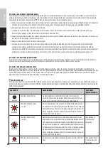
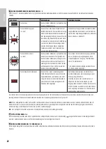
Page 10: ...ts the status is displayed on all channels Protect permanently lit The device has encountered a fatal fault To protect the device and connected speaker the device is switched to standby This status is generally displayed on all channels Power supply overtemperature amplifier board overtemperature DC voltage signal at the output DSP error Turn off the device and allow it to cool Disconnect all inpu...

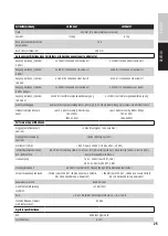
Page 11: ...ON 1 2 3 4 DIP TECHNICAL DATA Item description LDIPA424T LDIPA412T Product type Power amplifier for fixed installations General data Audio channels 4 Output circuit Class D Power supply Wide range switching power supply with PFC power factor correction filter Power supply connector 3 pole power supply socket IEC Auto standby mode Yes Switchable On Off Time to auto standby 20 min without audio inpu...

Page 12: ...e diameter Minimum diameter max AWG of cable cross section is 1 5 mm 16 AWG Maximum diameter min AWG of cable cross section is 3 31 mm 12 AWG Expansion slots Yes For optional Ethernet or Ethernet Dante cards Cooling Passive temperature controlled active two zone cooling with airflow from front to back to the side Operating voltage 100 240 V Mains fuse T10AL 100 120 V T5AL 220 240 V Inrush current ...

Page 13: ... Hz 22 kHz Low Z OUT 3 dB 50 Hz 23 kHz High Z OUT 3 dB Input impedance 40 kOhm symmetrical input design instrumentation speaker Signal to noise ratio 105 dB Low Z SPK OUT 18 dBu CH gain center 0 dB 20 kHz bandwidth A rated 104 dB Low Z SPK OUT 18 dBu CH gain center 0 dB 20 kHz bandwidth A rated Channel crosstalk 83 dB at 1 kHz Common mode rejection CMRR IEC 55 dB 1 kHz Gain Inf to 27dB IN OUT Pote...

Page 14: ... This equipment has been tested and found to comply with the limits for a Class B digital device pursuant to Part 15 of the FCC Rules These limits are designed to provide reasonable protection against harmful interference in a residential installation This equipment generates uses and can radiate radio frequency energy and if not installed and used in accordance with the instructions may cause har...

Page 15: ...n Sie alle in Ihrem Land geltenden Entsorgungsgesetze Trennen Sie bei der Entsorgung der Verpackung bitte Kunststoff und Papier bzw Kartonagen voneinander 22 Kunststoffbeutel müssen außer Reichweite von Kindern aufbewahrt werden 23 Sämtliche vom Benutzer vorgenommenen Änderungen und Modifikationen denen die für die Einhaltung der Richtlinien verantwortliche Partei nicht ausdrücklich zugestimmt hat...

Page 16: ... Klemme einer Schutzerde Erdung EIN Strom Um den Anschluss an das Stromnetz anzuzeigen zumindest für Netzschalter oder deren Positionen und alle Fälle in denen die Sicherheit betroffen ist AUS Strom Um die Trennung vom Netz anzuzeigen zumindest für Netzschalter oder deren Positionen und alle Fälle in denen die Sicherheit betroffen ist ACHTUNG HOHE LAUTSTÄRKEN BEI AUDIOPRODUKTEN Dieses Gerät ist fü...

Page 17: ...ichen Funktionalität wie die Ethernet Erweiterungskarte plus Dante Konnektivität Fehlerrelais mit Klemmenblockanschlüssen pro Kanalpaar Universelles Weitbereichs PFC Schaltnetzteil Temperaturgeregelte aktive Kühlung mit geräuscharmen Lüftern in 2 Zonen LIEFERUMFANG 1 x LD Systems IPA 424 T bzw IPA 412 T Installationsverstärker mit vormontierten Rackwinkeln 2 x 6 polige Klemmblöcke für die Audioein...

Page 18: ...nliegt am Lautsprecherausgang CH1 ausgegeben wird und ein Signal das am Line Eingang IN2 anliegt am Laut sprecherausgang CH2 Das Gleiche trifft auch für die Kanäle 3 und 4 zu Die entsprechenden Pegelsteller arbeiten unabhängig voneinander PAR Parallel Modus Im Parallel Modus wird ein Signal das am Line Eingang IN1 anliegt an den Lautsprecherausgängen CH1 und CH2 ausgegeben der Line Eingang IN2 ist...

Page 19: ...nd 4 die DSP Presets für die Lautsprecherausgänge 1 2 und 3 4 Die Beschreibung der Presets und die entsprechenden DIP Schalter Positionen finden Sie in der Tabelle unterhalb BILD DIP Schalter 3 DIP Schalter 4 DSP Preset CH1 2 CH3 4 Anwendung ON DIP OFF OFF Alle Kanäle Flat Fullrange Lautsprecher ON 1 2 3 4 DIP OFF ON High Pass Filter auf allen Kanälen HPF 95Hz LR 24dB Satelliten Lautsprecher ON DI...

Page 20: ...ubehörs Derzeit ist der DIP Schalter ohne Funktion DIP SCHALTER 4 REM LOCK REMOTE LOCK Bringen Sie den DIP Schalter 4 in die Position ON um alle Bedienelemente des Geräts zu sperren Pegelsteller DIP Schalter Schalter für den Kanalmodus und STANDBY Taster die Anzeige LED REM LOCK leuchtet dabei permanent Um die Sperrung der Bedienelemente zu beenden bringen Sie den DIP Schalter in die Position OFF ...

Page 21: ...amikbereich um bis zu 10dB erhöht Eine Ethernet Dante Erweiterungskarte mit der gleichen Funktionalität wie die Ethernet Erweiterungskarte plus Dante Konnektivität ON 1 2 3 4 DIP ON 1 2 3 4 DIP ON 2 3 4 DIP ON 1 2 3 4 DIP ON 2 3 4 DIP ON 1 2 3 4 DIP ON 1 2 3 4 DIP ON 1 2 3 4 DIP ON 1 2 3 4 DIP ON 1 2 3 4 DIP ON 2 3 4 DIP ON 1 2 3 4 DIP ON 2 3 4 DIP ON 1 2 3 4 DIP ON 1 2 3 4 DIP ON 1 2 3 4 DIP ON 2...

Page 22: ...t hat einen schwerwiegenden Fehler festgestellt Um das Gerät und die angeschlossenen Lautsprecher zu schüt zen wird das Gerät in den Wartezustand gebracht Dieser Status wird generell in allen Kanälen angezeigt Netzteil Übertemperatur Verstärker Plati ne Übertemperatur Gleichspannungssignal am Ausgang DSP Fehler Schalten Sie das Gerät aus und lassen es abkühlen Ziehen Sie alle Eingangs und Ausgangs...

Page 23: ...CH ENGLISH BELEGUNG DER KLEMMBLOCKANSCHLÜSSE UND SETUP BEISPIELE ON 2 3 4 DIP ON 1 2 3 4 DIP ON 1 2 3 4 DIP ON 1 2 3 4 DIP ON 1 2 3 4 DIP ON 1 2 3 4 DIP ON 1 2 3 4 DIP ON 1 2 3 4 DIP ON 2 3 4 DIP ON 1 2 3 4 DIP ...

Page 24: ...ngänge Remote Bus Audioeingang Eingangsanschlüsse 6 Pol Klemmblock Abstand 3 81 mm Remote EIN AUS RJ45 Service Anschluss Micro USB Typ B Ausgänge 4 x spannungsversorgte Lautsprecherausgänge Low Z mindestens 4 Ohm High Z 70 V und 100 V Fehlererken nung 2 x NO NC Relaisausgänge gekoppelt Ausgangsanschlüsse Lautsprecherausgänge 4 Pol Klemmblockanschlüsse Abstand 5 08 mm Fehlerrelais 2 x 3 Pol Klemmbl...

Page 25: ... Gleichstromschutz Mindestlastimpedanz pro Kanal Low Z 4 Ohm einseitig 8 Ohm Bridge 70V 21 Ohm 100V 42 Ohm Low Z 4 Ohm einseitig 8 Ohm Bridge 70V 42 Ohm 100V 84 Ohm Performance Spezifikationen Eingangsempfindlichkeit nominal 5 dBu Sinussignal 1 kHz Gain Max Eingangsübersteuerung nominal 19 dBu Sinussignal 1 kHz Klirrfaktor THD N 0 03 Low Z SPK OUT 18 dBu 20 Hz 20 kHz Intermodulationsverzerrun gen ...

Page 26: ...Personenschäden durch unkontrollierte Abfallentsorgung zu vermeiden Bitte entsorgen Sie dieses Produkt getrennt von anderen Abfällen und führen es zur Förderung nachhaltiger Wirtschaftskreisläufe dem Recycling zu Als Privatkunde erhalten Sie Informationen zu umweltfreundlichen Entsorgungsmöglichkeiten über den Händler bei dem das Produkt erworben wurde oder über die entsprechenden regionalen Behör...

Page 27: ......

Page 28: ...Adam Hall GmbH Adam Hall Str 1 61267 Neu Anspach Germany Phone 49 6081 9419 0 adamhall com ld systems com REV 02 ...

Reviews: