7
DEUTSCH
OUTPUT SECTION
ON
1
2
3 4
DIP
ON
1
2
3 4
DIP
ON
2 3 4
DIP
ON
1 2 3 4
DIP
ON
2 3 4
DIP
ON
1 2 3 4
DIP
ON
1
2
3 4
DIP
ON
1
2
3 4
DIP
11
15
12
13
14
11
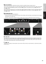
SPEAKER OUTPUTS CH1 - CH4
Four 4-pole terminal block connectors CH1 to CH4 for the connection of speakers in the previously selected operating mode (100 V, 70 V, 4 Ohm).
You can find the pin assignment corresponding to the speaker system on the label between terminal block connections. The packaging includes
suitable terminal blocks. Within DIP switch block no.12, use DIP switches 1 and 2 to select the desired operating mode.
12
HI-Z / LOW-Z AND PRESET
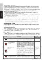
Use DIP switch 1 and 2 to select the operating mode for each pair of speaker outputs 1/2 and 3/4.
Speaker outputs 1 and 2: Move DIP switch 2 to the ON position for HI-Z operation (100V, 70V) and to the OFF position for LOW-Z operating mode (4 OHM).
Speaker outputs 3 and 4: Move DIP switch 1 to the ON position for HI-Z operation (100V, 70V) and to the OFF position for LOW-Z operating mode (4 OHM).
Use DIP switch 3 and 4 to select the DSP preset for speaker outputs 1/2 and 3/4. The description of the preset and corresponding DIP switch positions
can be found in the table below.
IMAGE
DIP switch 3
DIP switch 4
DSP preset
CH1-2
CH3-4
Use
ON
DIP
OFF
OFF
All channels flat
Full-range speaker
ON
1
2
3 4
DIP
OFF
ON
High-pass filter on all
channels (HPF 95Hz,
LR 24dB)
Satellite speaker
ON
DIP
ON
OFF
CH1 + CH2: High-pass
filter (HPF 95Hz, LR
24dB)
Satellite speaker
CH3 + CH4: Low-pass
filter (LPF 95Hz, LR 24dB
/ HPF 30Hz, BW 24dB)
Subwoofer
ON
DIP
ON
ON
Low-pass filter on all
channels
(LPF 95Hz, LR 24dB / HPF
30Hz, BW 24dB)
Subwoofer
13
SYSTEM SETTINGS AND RESET
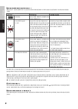
DIP SWITCH 1 STANDBY
To activate the automatic standby function, move DIP switch 1 to the ON position. If the standby switch is activated, the amplifier will automatically
switch to standby mode (energy consumption reduction) after approximately 20 minutes of no audio signal. If there is an audio signal again,
standby mode automatically ends and the amplifier is ready for operation again after about three seconds; the standby LED flashes white during
this time. The STANDBY LED on the front of the device is white during normal operation and red when standby mode is activated. Standby mode can
also be manually terminated by pressing the standby button on the front of the amplifier.
1
2
3 4
1
2
3 4
1
2
3 4
Summary of Contents for IPA 412 T
Page 27: ......


