background image

LD-Systems

Page 6

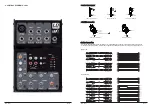
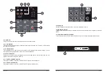
 4. CONTROL ELEMENTS - LAX5

LD-Systems

Page 11

    XLR Type Unbalanced 

    XLR Type  alanced 

B

Pin3 (-)

Pin2 (+)

Pin1 (   )

(Linked to Pin1 manually,     )

Pin1 (   )

Pin2 (+)

Pin3 (-)

Tip

Ring

Sleeve

Tip
Ring

Sleeve

Tip

Ring

Sleeve

1

2

3

1
2

3

1
2
3

TIP RING SLEEVE

SLEEVE RING TIP

TIP RING SLEEVE

2

1

3

12

3

12

3

Tip

Ring

Sleeve

Tip
Ring

Sleeve

Tip

Ring

Sleeve

1

2

3

1
2

3

1
2
3

TIP RING SLEEVE

SLEEVE RING TIP

TIP RING SLEEVE

2

1

3

12

3

12

3

Tip

Ring

Sleeve

Tip
Ring

Sleeve

Tip

Sleeve

Tip

Sleeve

Tip

Sleeve

Cent e

r

Cent e

r

Centre

Screen

Screen

Screen

1

2
3

Tip

Ring

Sleeve

1

2

3

1
2
3

TIP SLEEVE

TIP SLEEVE

TIP RING SLEEVE

TIP RING SLEEVE

12

3

21

3

21

3

Tip

Ring

Sleeve

1
2
3

Tip

Sleeve

1
2
3

TIP RING SLEEVE

TIP SLEEVE

12

3

12

3

 SLEEVE TIP

SLEEVE  

RING TIP

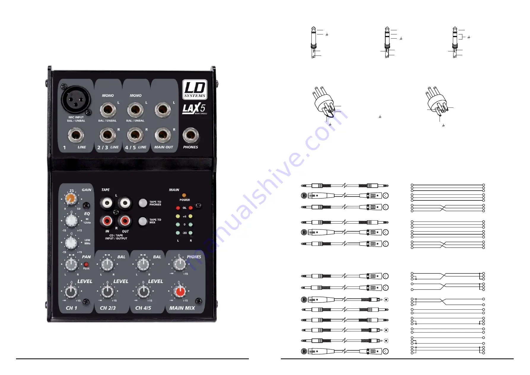
- For XLR connector

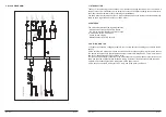
For these applications the unit provides 1/4" TRS and XLR connectors to easily interface with most 
professional audio devices. Follow the configuration examples below for your particular connection.

Unbalanced

- In-line Connection

Balanced


TRS Type Unbalanced 

Sleeve

Tip

+

TRS Type Balanced

Tip

Ring

Sleeve

+

-

TRS Type Unbalanced

Tip

Ring

Sleeve

+

- For 1/4” Phone jack

Summary of Contents for LAX5

Page 1: ...d to Adam Hall All features and content might be changed without prior notice Photocopying translation or reproduction of any part of this manual without written permission is forbidden Copyright 2007...

Page 2: ...erating this unit for the first time All rights reserved to Adam Hall GmbH All features and content might be changed without prior notice Photocopying translation or reproduction of any part of this m...

Page 3: ...lt in fire Keep product away from naked flames Read these instructions Follow all instructions Keep these instructions Do not discard Heed all warnings Only use attachments accessories specified by th...

Page 4: ...1 kHz 0 dB to 50 dB Main Phones 106 dBu 10 Hz to 200 kHz Distortion 20 Hz to 20 kHz Noise CMRR Crosstalk High 15 dB 12 kHz Low 15 dB 80 Hz Maximum Rated Output 22 dBu Maximum Input Levels Mic Input 12...

Page 5: ...RS sockets A 2 Band EQ for the mono input 2 track in and outputs Balanced output with TRS sockets 3 GETTING STARTED 3 1 Please check the AC voltage available in your country before connecting your LAX...

Page 6: ...eeve Tip Sleeve Tip Sleeve Cent e r Cent e r Centre Screen Screen Screen 1 2 3 Tip Ring Sleeve 1 2 3 1 2 3 TIP SLEEVE TIP SLEEVE TIP RING SLEEVE TIP RING SLEEVE 1 2 3 2 1 3 2 1 3 Tip Ring Sleeve 1 2 3...

Page 7: ...e following examples on how to wire up your sys tem LD Systems Page 7 4 1 THE MONO CHANNEL You can connect balanced low impedance mirophones or a low level signal to the XLR socket On the 1 4 line jac...

Page 8: ...g device such as a tape deck in order to record the mix The signal is the same as that of the main mix 4 13 TAPE TO PHONES SWITCH Pressing this switch will route the CD TAPE INPUT signal to the headph...

Reviews: