LD-Systems
Page 10
5. INSTALLATION AND CONNECTION
Now that you have a rough idea of the mixers functions you should be able to operate it. However,
we strongly recommend you read the following section carefully as it contains a number of useful
tips on how to operate the mixer correctly.
- Make sure the input- and master levels of the LAX5 are turned down before you connect micro-
phones and instruments to the inputs.
- Properly connect all external devices such as mics, power amplifi ers, speakers, effects processor
etc.
- Be sure to lay the cables safely to avoid injury or damage to your equipment.
- Set the output level of your mixer or the connected power amplifi er to no more than 75%.
- Set the PHONES level to no more than 50%.
- Position HI and LOW EQ controls on middle position.
- Position the panorama and balance (PAN/BAL) controls in center position.
- While speaking/singing into the mic (or playing the instrument), adjust the channel Level control so
that the channel PEAK LED (in the case of the fi rst channel) will blink occasionally, in this way you
will maintain good headroom and an ideal dynamic range.
- You can shape the tone of each channel by adjusting the equalizer controls as desired.
- Now repeat the same sequence for all other input channels. Keep an eye on the main LED chain
and make sure it does not move up too far into the red section.
5.1 AUDIO CONNECTIONS
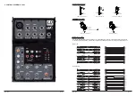
For maximum fl exibility both XLR and 1/4 “ TRS connectors are available on this unit. There are a
number of ways to connect your equipment. Read the following chapter to learn more.
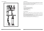
Wiring confi guration
Either the 1/4” TRS phone jack or XLR connectors can be wired in balanced and unbalanced modes,
depending on the equipment used. Please see the following examples on how to wire up your sys-
tem:
LD-Systems
Page 7
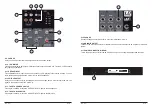
4.1 - THE MONO CHANNEL
You can connect balanced low impedance mirophones or a low
level signal to the XLR socket. On the 1/4” line jack you can con-
nect line level instruments such as drum computers, synthesizers,
effects processors or any other line level devices.
Note: It is not possible to use both inputs simultaneously
4.2 - ADJUSTING THE INPUT LEVEL (GAIN)
Adust this level so that the peak LED lights up occasionally, the
peak LED should not be lit constantly, in this case your signal may
be distorted.
4.3 - 2-BAND EQ
The fi rst channel of the mixer is equipped with a simple 2 Band EQ
for adjusting the sound.
HI
This is the Treble control. It can be used to eliminate unwanted high
frequencies or to give your signal mor brilliance and presence. It
ranges from -15dB to +15dB with a center frequency of 12kHz.
LOW
This is the bass control. It can be used to boost a male voice, a kick-
drum or a bass guitar. The gain ranges from -15dB to +15dB with a
center frequency at 80Hz.
4.4 - PAN / BAL
The fi rst channel of the LAX5 has a PAN control wheras the other
two stereo cahnnels have a balance control. Both controls are used
to to distribute the incomming signal across the left and right chan-
nel of the main output.
4.5 - PEAK-LED
The fi rst channel of the LAX5 is equipped with a peak LED. It lights
up, when the signal is about to distort (6 dB below actually distort-
ing). When this LED is lit it means, that the maximal level has been
reached.
4.6 - LEVEL
Here you can adjust the volume of the cannel and consequently the
level of the signal which is passed on to the main mix.
4.7 - THE STEREO CHANNELS
The stereo channels are counfi gured as stereo pairs with TRS jack
inputs. Connect mono signals to the left input.
4.8
-
MAIN MIX
Herewith you can adjust the overall level of the signal that is sent to
the main outputs and to the tape output.
1
2
3
4
5
6


