background image

IT

ALIANO

POLSKI

ESP
AÑOL

FRANCAIS

DEUTSCH

ENGLISH

3

ENGLISH

YOU‘VE MADE THE RIGHT CHOICE!

We have designed this product to operate reliably over many years. LD Systems stands for this with its name and many years of experience 

as a manufacturer of high-quality audio products. Please read this User‘s Manual carefully, so that you can begin making optimum use of 

your LD Systems product quickly. You can find more information about 

LD-SYSTEMS

 at our Internet site  WWW.

LD-SYSTEMS

.COM

PREVENTIVE MEASURES

1. Please read these instructions carefully. 

2. Keep all information and instructions in a safe place. 

3. Follow the instructions. 

4. Observe all safety warnings. Never remove safety warnings or other information from the equipment. 

5. Use the equipment only in the intended manner and for the intended purpose. 

6. Use only sufficiently stable and compatible stands and/or mounts (for fixed installations). Make certain that wall mounts are properly installed and 

secured. Make certain that the equipment is installed securely and cannot fall down. 

7. During installation, observ  e the applicable safety regulations for your country. 

8. Never install and operate the equipment near radiators, heat registers, ovens or other sources of heat. Make certain that the equipment is 

always installed so that is cooled sufficiently and cannot overheat. 

9. Never place sources of ignition, e.g., burning candles, on the equipment. 

10. Ventilation slits must not be blocked. 

11. This appliance is designed exclusively for indoor use, do not use this equipment in the immediate vicinity of water (does not apply 

to special outdoor equipment - in this case, observe the special instructions noted below). Do not expose this equipment to flammable 

materials, fluids or gases. 

12. Make certain that dripping or splashed water cannot enter the equipment. Do not place containers filled with liquids, such as vases or 

drinking vessels, on the equipment. 

13. Make certain that objects cannot fall into the device. 

14. Use this equipment only with the accessories recommended and intended by the manufacturer. 

15. Do not open or modify this equipment. 

16. After connecting the equipment, check all cables in order to prevent damage or accidents, e.g., due to tripping hazards. 

17. During transport, make certain that the equipment cannot fall down and possibly cause property damage and personal injuries.

18. If your equipment is no longer functioning properly, if fluids or objects have gotten inside the equipment or if it has been damaged in 

another way, switch it off immediately and unplug it from the mains outlet (if it is a powered device). This equipment may only be repaired 

by authorized, qualified personnel. 

19. Clean the equipment using a dry cloth. 

20. Comply with all applicable disposal laws in your country. During disposal of packaging, please separate plastic and paper/cardboard. 

21. Plastic bags must be kept out of reach of children.

FOR EQUIPMENT THAT CONNECTS TO THE POWER MAINS:

22. CAUTION: If the power cord of the device is equipped with an earthing contact, then it must be connected to an outlet with a protective 

ground. Never deactivate the protective ground of a power cord. 

23. If the equipment has been exposed to strong fluctuations in temperature (for example, after transport), do not switch it on immediately. 

Moisture and condensation could damage the equipment. Do not switch on the equipment until it has reached room temperature. 

24. Before connecting the equipment to the power outlet, first verify that the mains voltage and frequency match the values specified on the 

equipment. If the equipment has a voltage selection switch, connect the equipment to the power outlet only if the equipment values and the 

mains power values match. If the included power cord or power adapter does not fit in your wall outlet, contact your electrician. 

25. Do not step on the power cord. Make certain that the power cable does not become kinked, especially at the mains outlet and/or power 

adapter and the equipment connector. 

26. When connecting the equipment, make certain that the power cord or power adapter is always freely accessible. Always disconnect the 

equipment from the power supply if the equipment is not in use or if you want to clean the equipment. Always unplug the power cord and 

power adapter from the power outlet at the plug or adapter and not by pulling on the cord. Never touch the power cord and power adapter 

with wet hands. 

27. Whenever possible, avoid switching the equipment on and off in quick succession because otherwise this can shorten the useful life of 

the equipment.

28. IMPORTANT INFORMATION: Replace fuses only with fuses of the same type and rating. If a fuse blows repeatedly, please contact an 

authorised service centre. 

29. To disconnect the equipment from the power mains completely, unplug the power cord or power adapter from the power outlet. 

30. If your device is equipped with a Volex power connector, the mating Volex equipment connector must be unlocked before it can be removed. 

However, this also means that the equipment can slide and fall down if the power cable is pulled, which can lead to personal injuries and/or 

other damage. For this reason, always be careful when laying cables. 

31. Unplug the power cord and power adapter from the power outlet if there is a risk of a lightning strike or before extended periods of disuse.

32. The device must only be installed in a voltage-free condition (disconnect the mains plug from the mains).

33. Dust and other debris inside the unit may cause damage. The unit should be regularly serviced or cleaned (no guarantee) depending on 

ambient conditions (dust etc., nicotine, fog) by qualified personnel to prevent overheating and malfunction.

34. Please keep a distance of at least 0.5 m to any combustible materials.

Summary of Contents for LDMEI1000G2

Page 1: ...LDMEI1000G WIRELESS IN EAR MONITORING SYSTEM USER S MANUAL BEDIENUNGSANLEITUNG MANUEL D UTILISATION MANUAL DE USUARIO INSTRUKCJA OBS UGI MANUALE D USO...

Page 2: ...36 40 MISE EN PLACE ET EN CAS DE PROBL ME 41 CARACT RISTIQUES 42 DECLARATIONS 43 ESPA OL MEDIDAS DE SEGURIDAD 44 45 INTRODUCCI N 45 COMPONENTES DEL SISTEMA 46 CONEXIONES CONTROLES E INDICADORES 47 48...

Page 3: ...sposal of packaging please separate plastic and paper cardboard 21 Plastic bags must be kept out of reach of children FOR EQUIPMENT THAT CONNECTS TO THE POWER MAINS 22 CAUTION If the power cord of the...

Page 4: ...lly about the existence of potential health risks Hearing damage due to high volume and prolonged exposure When in use this product is capable of producing high sound pressure levels SPL that can lead...

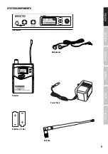
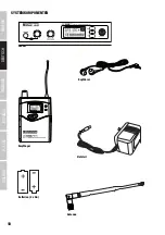
Page 5: ...ITALIANO POLSKI ESPA OL FRANCAIS DEUTSCH ENGLISH 5 SYSTEM COMPONENTS POWER SET POWER SET Transmitter Headphones Receiver Power Pack Batteries 2 x AA Antenna...

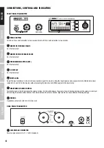
Page 6: ...optimal signal to noise ratio bring the input signal as close as possible to the 0dB indicator level indicator AF L and AF R in the display without exceeding the distortion limit PEAK segment in the l...

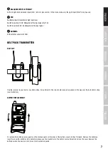
Page 7: ...4 ANTENNA BNC antenna connector 50 Ohm BELT PACK TRANSMITTER BELT CLIP Clip the receiver to your belt or a suitable strap For optimum fit the clip should always be pushed all the way over the belt an...

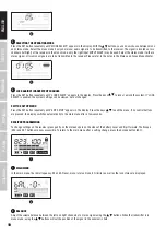
Page 8: ...he red LED blinks BODY PACK RECEIVER 10 1 ON OFF SWITCH AND VOLUME CONTROL FOR EARPHONE HEADPHONE OUTPUT To switch on turn the knob to the right clockwise past the snap in point To switch off turn the...

Page 9: ...System Setup 8 ARROW DOWN DECREASE VALUE See Chapter System Setup 9 ESC BUTTON Press this button to return to the main menu 10 SET BUTTON See Chapter System Setup SYSTEM SETUP TRANSMITTER PROGRAMMING...

Page 10: ...the system If LOCK SELECT is enabled the system settings can be viewed but not changed EXIT THE SETUP MENU Press the SET button repeatedly until EXIT SETUP appears in the display Press the keys to ex...

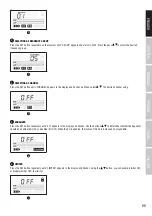
Page 11: ...the display and flashes and then select the desired channel using 5 5 EQUALIZER Press the SET button repeatedly until EQ appears in the display and flashes Use the buttons to determine whether the Eq...

Page 12: ...ase select the 0 setting To ensure the transmission of a stereo audio signal in the stereo mode both the transmitter and the receiver have to be in stereo mode and an audio signal has to be present at...

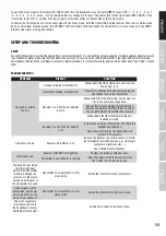
Page 13: ...the connection between power supply and transmitter Turn on the transmitter Receiver is on but the RF indicator is not lit Make certain that the transmitter and receiver are set to the same radio fre...

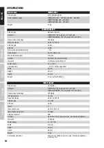
Page 14: ...Up Down Set Volume Escape Indicators LC Display Low Battery RF Power supply 2 x 1 5 V AA Operating time 12 hrs battery dependent Width 65 mm Height 90 mm Depth 24 mm Weight 0 1 kg without batteries L...

Page 15: ...ted waste collection system This symbol on the product or on its documents indicates that the device may not be treated as household waste This is to avoid environmental damage or personal injury due...

Page 16: ...steckdose sofern es sich um ein aktives Ger t handelt Dieses Ger t darf nur von autorisiertem Fachpersonal repariert werden 19 Verwenden Sie zur Reinigung des Ger ts ein trockenes Tuch 20 Beachten Sie...

Page 17: ...AUDIOPRODUKTEN Dieses Ger t ist f r den professionellen Einsatz vorgesehen Der kommerzielle Betrieb dieses Ger ts unterliegt den jeweils g ltigen nationalen Vorschriften und Richtlinien zur Unfallver...

Page 18: ...18 DEUTSCH FRANCAIS ESPA OL ENGLISH ITALIANO POLSKI SYSTEMKOMPONENTEN POWER SET POWER SET Sender Kopfh rer Empf nger Netzteil Batterien 2 x AA Antenne...

Page 19: ...optimalen Rauschabstand zu erzielen bringen Sie das Eingangssignal m glichst in den Bereich der 0dB Anzeige Pegelanzeige AF L und AF R im Display ohne dabei die Verzerrungsgrenze zu berschreiten PEAK...

Page 20: ...Antennenanschluss 50 Ohm BELT PACK SENDER G RTELCLIP Befestigen Sie den Empf nger mit dem Clip am G rtel oder einem geeigneten Gurt F r optimalen Sitz sollte der Clip stets vollst ndig auf den G rtel...

Page 21: ...die rote LED blinkt TASCHENEMPF NGER 10 1 EIN AUS SCHALTER UND LAUTST RKEREGLER OHR KOPFH RERAUSGANG Zum Einschalten den Knopf nach rechts im Uhrzeigersinn ber den Rastpunkt hinaus drehen Zum Ausscha...

Page 22: ...rz auf Leuchtet sobald ein HF Signal anliegt Funkfrequenz von Sender und Empf nger m ssen bereinstimmen 7 PFEIL NACH OBEN WERT ERH HEN Bedienung siehe Kapitel Systemeinstellungen 8 PFEIL NACH UNTEN WE...

Page 23: ...nal oder zwei Mono Signale an den Empf nger bertragen werden sollen Hinweise dazu im Kapitel Stereo und Focus Betriebsart 4 5 SPERREN GEGEN UNBEABSICHTIGTES VERSTELLEN Dr cken Sie die SET Taste so oft...

Page 24: ...ken Sie die SET Taste am Empf nger so oft bis die Anzeige GROUP erscheint und zu blinken beginnt Dr cken Sie nun bzw um die gew nschte Frequenzgruppe auszuw hlen 4 4 AUSWAHL EINES KANALS Dr cken Sie d...

Page 25: ...rscheint und blinkt Mit Hilfe der bzw Tasten k nnen Sie nun die Stereo Betriebsart aktivieren FO OFF In der Stereo Betriebsart sind die beiden Eingangssignale des Senders jeweils links und rechts ber...

Page 26: ...nn nun vom Anwender direkt am Empf nger mit Hilfe der Tasten bzw eingestellt werden wobei insgesamt 31 Stufen zur Verf gung stehen Um das Mono Signal das am rechten Eingang INPUT RIGHT des Senders anl...

Page 27: ...tellen Sie sicher dass die Antenne des Senders richtig montiert ist Empf nger Ist eingeschaltet und die RF Anzeige leuchtet Erh hen Sie die Lautst rke am Empf nger und berpr fen Sie die Verbindung des...

Page 28: ...et Volume Escape Anzeigeelemente LC Display Low Battery RF Stromversorgung 2 x 1 5 V AA Betriebsdauer 12 Std batterieabh ngig Breite 65 mm H he 90 mm Tiefe 24 mm Gewicht 0 1 kg ohne Batterien LDMEI100...

Page 29: ...menten weist darauf hin dass das Ger t am Ende der Produktlebenszeit nicht zusammen mit dem normalen Hausm ll entsorgt werden darf um Umwelt oder Personensch den durch unkontrollierte Abfallentsorgung...

Page 30: ...t appareil ne doit tre r par que par un personnel autoris 19 Pour le nettoyage de l appareil utilisez un chiffon sec 20 Observez toutes les r glementations en vigueur dans votre pays pour mettre l app...

Page 31: ...AUX SONORES LEV S SUR LES PRODUITS AUDIO Cet appareil a t con u en vue d une utilisation professionnelle L utilisation commerciale de cet appareil est soumise aux r glementations et directives en vigu...

Page 32: ...32 DEUTSCH FRANCAIS ESPA OL ENGLISH ITALIANO POLSKI COMPOSANTS DU SYST ME POWER SET POWER SET metteur de poche couteurs R cepteur HF Bloc Secteur Piles 2 x LR06 AA A rienne...

Page 33: ...Pour obtenir un rapport signal bruit optimal r glez le gain d entr e de fa on ce que le niveau du signal se rapproche le plus possible du 0 dB sur les chelles AF L et AF R dans l affichage sans pour a...

Page 34: ...RIENNE Connecteur antenne BNC imp dance 50 Ohms METTEUR DE POCHE PINCE CEINTURE Fixez le r cepteur par sa pince sur votre ceinture ou tout autre l ment Pour une tenue en place optimale la pince doit...

Page 35: ...DE POCHE 10 1 INTERRUPTEUR MARCHE ARR T R GLAGE DU NIVEAU DE SORTIE CASQUE COUTEURS Pour allumer le r cepteur tournez le potentiom tre dans le sens des aiguilles d une montre apr s le d clic Pour tein...

Page 36: ...s fr quences utilis es par l metteur et le r cepteur doivent correspondre 7 FL CHE VERS LE HAUT AUGMENTATION DES VALEURS Voir le chapitre R glages syst me 8 FL CHE VERS LE BAS R DUCTION DES VALEURS Vo...

Page 37: ...d tails sur le sujet dans la section Modes Stereo et Focus 4 5 VERROUILLAGE CONTRE LES MANIPULATIONS ACCIDENTELLES Appuyez plusieurs fois sur la touche SET jusqu ce que la mention LOCK SELECT apparais...

Page 38: ...ur jusqu ce que la mention GROUP apparaisse et commence clignoter Appuyez alors sur les touches pour choisir le num ro du groupe de fr quences d sir 4 4 CHOIX D UN CANAL Appuyez plusieurs fois sur la...

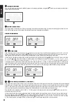
Page 39: ...oisir le mode Stereo Appuyez plusieurs fois sur la touche SET jusqu ce que la mention FO OFF ou FO ON apparaisse et clignote l cran Avec les touches activez le mode Stereo FO OFF En mode Stereo les de...

Page 40: ...r le r cepteur L utilisateur peut modifier leur niveau relatif directement sur l metteur avec les touches selon 31 pas Si vous d sirez r duire dans le mix le niveau du signal mono arrivant sur l entr...

Page 41: ...contact visuel direct V rifiez que l antenne de l metteur est mont e correctement R cepteur Allum et l indicateur HF est allum Montez le volume sur le r cepteur et v rifiez le branchement des couteur...

Page 42: ...e Escape Indicateurs cran LCD indicateur Low Battery RF Alimentation 2 piles 1 5 Volt type LR06 AA Autonomie 12 heures avec des piles de qualit Largeur 65 mm Hauteur 90 mm Profondeur 24 mm Poids 0 1 k...

Page 43: ...sur le produit ou sur la documentation correspondante indique qu en fin de vie le produit ne doit pas tre jet avec les d chets normaux afin d viter tout dommage l environnement ou aux personnes cons c...

Page 44: ...be reparar el equipo 19 Para limpiar el equipo utilice un pa o seco 20 Procure seguir las normas vigentes en su pa s sobre reciclaje de desechos Separe los componentes de pl stico papel y cart n del p...

Page 45: ...exclamaci n dentro de un tri ngulo equil tero advierte al usuario de la existencia de importantes instrucciones de uso y mantenimiento ADVERTENCIA ALTO VOLUMEN Este equipo se destina a un uso profesi...

Page 46: ...46 DEUTSCH FRANCAIS ESPA OL ENGLISH ITALIANO POLSKI COMPONENTES DEL SISTEMA POWER SET POWER SET Transmisor Auriculares Receptor Adaptador de corriente 2 bater as tipo AA Antena...

Page 47: ...L DE ENTRADA Control de nivel de entrada Para alcanzar una relaci n se al ruido ptima se intentar que el nivel est cerca de 0 dB indicadores AF L y AF R de la pantalla pero sin llegar a distorsionar i...

Page 48: ...entrada 4 ANTENA Conector de antena BNC de 50 ohmios RECEPTOR DE PETACA CLIP DE CINTUR N El receptor se cuelga de un cintur n mediante el clip Se recomienda deslizar el clip de la petaca hasta el fond...

Page 49: ...mente Sustituya las bater as cuando el LED rojo parpadee RECEPTOR DE PETACA 10 1 INTERRUPTOR DE ENCENDIDO Y CONTROL DE NIVEL DE AURICULARES Para encender girar el bot n hacia la derecha sentido horari...

Page 50: ...e al de radiofrecuencia La frecuencia del transmisor debe coincidir con la del receptor 7 FLECHA ARRIBA AUMENTAR EL VALOR Consulte la secci n Configuraci n del sistema 8 FLECHA ABAJO DISMINUIR EL VALO...

Page 51: ...receptor Consulte las notas sobre los modos Est reo y Foco 4 5 BLOQUEO CONTRA CAMBIOS ACCIDENTALES Pulse varias veces el bot n SET hasta que en pantalla se muestre LOCK SELECT Pulse los botones o par...

Page 52: ...s o para seleccionar el grupo de frecuencias deseado 4 4 SELECCI N DEL CANAL Pulse varias veces el bot n SET hasta que en pantalla se muestre CHANNEL parpadeando a continuaci n seleccione el canal des...

Page 53: ...o FO OFF parpadeando Mediante los botones o podr activar el modo Est reo FO OFF En el modo Est reo las dos se ales de entrada al transmisor se escuchar n en unos auriculares conectados al receptor co...

Page 54: ...al transmisor y se reproducen en mono El usuario puede variar el balance de las dos se ales mediante los botones o del receptor disponiendo de 31 niveles Para una se al mono aplicada a la entrada de l...

Page 55: ...r y el receptor hay una l nea directa Aseg rese de que la antena del transmisor est correctamente montada Receptor est encendido y se ilumina el LED de RF Suba el nivel del receptor y compruebe la con...

Page 56: ...Indicadores Pantalla LCD Bater a baja RF Alimentaci n el ctrica 2 pilas de 1 5 V tipo AA Autonom a 12 horas en funci n de las pilas Ancho 65 mm Altura 90 mm Fondo 24 mm Peso 0 1 kg sin bater as LDMEI...

Page 57: ...ectiva El s mbolo que aparece sobre el producto o en la documentaci n adjunta indica que al final de la vida til del equipo no deber desecharlo con los dem s residuos dom sticos con el fin de evitar p...

Page 58: ...e zosta o uszkodzone w inny spos b nale y je natychmiast wy czy i od czy od gniazda sieciowego je li urz dzenie jest aktywne Napraw takiego urz dzenia mo e wykona tylko autoryzowany personel specjalis...

Page 59: ...profesjonalnych zastosowa Komercyjne stosowanie tego urz dzenia podlega obowi zuj cym w danym kraju przepisom i wytycznym dotycz cym zapobiegania wypadkom Firma Adam Hall jest jako producent zobowi z...

Page 60: ...60 DEUTSCH FRANCAIS ESPA OL ENGLISH ITALIANO POLSKI ELEMENTY SYSTEMU POWER SET POWER SET Nadajnik S uchawki Odbiornik Zasilacz sieciowy Baterie 2 x AA Antena...

Page 61: ...Aby uzyska optymalny stosunek sygna u do szumu nale y ustawi sygna wej ciowy w miar mo liwo ci w zakresie wskazania 0 dB wska nik poziomu AF L i AF R na wy wietlaczu nie przekraczaj c przy tym granicy...

Page 62: ...one 4 ANTENA Przy cze antenowe BNC 50 PRZE CZNIK WZMACNIANIA I WYCISZANIA SYGNA U ZACZEP NA PASEK Zamocowa odbiornik za pomoc zaczepu do paska spodni lub innego pasa Aby zapewni optymalne mocowanie od...

Page 63: ...Y 10 1 W CZNIK WY CZNIK I REGULATOR G O NO CI WYJ CIA S UCHAWEK DOUSZNYCH NAG OWNYCH Aby w czy nale y przekr ci pokr t o w prawo w kierunku ruchu wskaz wek zegara do momentu klikni cia Aby wy czy nale...

Page 64: ...tlny przy w czaniu Zapala si gdy pojawi si sygna o wysokiej cz stotliwo ci Cz stotliwo radiowa nadajnika i odbiornika musi by taka sama 7 STRZA KA W G R ZWI KSZANIE WARTO CI Obs uga patrz punkt Ustawi...

Page 65: ...dotycz ce tego trybu podano w punkcie Tryb pracy stereo i focus 4 5 BLOKADA PRZYPADKOWEJ ZMIANY USTAWIE Naciska przycisk SET dop ki na wy wietlaczu nie pojawi si napis LOCK SELECT Za pomoc przycisku l...

Page 66: ...orniku dop ki na wy wietlaczu nie pojawi si migaj cy napis GROUP Za pomoc przycisku lub wybra dan grup cz stotliwo ci 4 4 WYB R KANA U Naciska przycisk SET dop ki na wy wietlaczu nie pojawi si migaj c...

Page 67: ...ET dop ki na wy wietlaczu nie poja wi si migaj cy napis FO OFF lub FO ON Za pomoc przycisku lub mo na teraz w czy tryb pracy stereo FO OFF W trybie pracy stereo oba sygna y wej ciowe nadajnika s s ysz...

Page 68: ...k g o no ci obu sygna w bezpo rednio na odbiorniku za pomoc przycisku lub przy czym cznie dost pnych jest 31 poziom w Aby sygna mono podawany na prawym wej ciu INPUT RIGHT nadajnika przenie na drugi p...

Page 69: ...adba o to aby nadajnik i odbiornik znajdowa y si w bezpo rednim kontakcie wzrokowym Prawid owo zamontowa anten nadajnika Odbiornik jest w czony i wy wietla si zakres cz stotliwo ci Zwi kszy g o no w o...

Page 70: ...i Up Down Set Volume Escape Wska niki Wy wietlacz LCD niski poziom na adowania baterii RF Zasilanie 2 x 1 5 V AA Czas pracy 12 godzin w zale no ci od baterii Szeroko 65 mm Wysoko 90 mm G boko 24 mm Wa...

Page 71: ...zanych z nim dokumentach wskazuje i urz dzenie po zako czeniu okresu u ytkowania nie mo e by utylizowane razem ze standar dowymi odpadami domowymi aby unikn szk d w rodowisku lub szk d na osobie powst...

Page 72: ...no pulito 20 Rispettare le leggi sullo smaltimento in vigore nel Paese di installazione Al momento di smaltire l imballo separare la plastica dalla carta e dal cartone 21 I sacchetti di plastica devon...

Page 73: ...roduttore Adam Hall tenuto per legge a informare espressamente gli utenti degli eventuali rischi per la salute Danni all udito provocati da un esposizione prolungata a un livello SPL elevato dall util...

Page 74: ...74 DEUTSCH FRANCAIS ESPA OL ENGLISH ITALIANO POLSKI COMPONENTI DEL SISTEMA POWER SET POWER SET Trasmettitore Auricolari Ricevitore Alimentatore Batterie n 2 AA Antenna...

Page 75: ...it di ingresso Per ottenere un rapporto segnale rumore ottimale avvicinare il segnale di ingresso il pi possibile a 0 dB indicatore di livello AF L e AF R sul display senza superare il limite di disto...

Page 76: ...ANTENNE Presa dell antenna BNC da 50 Ohm INTERRUTTORE DI REGOLAZIONE DEL GUADAGNO E MUTE CLIP CINTURA Il ricevitore si fissa alla cintura o a una cinghia idonea con la clip Per un fissaggio ottimale...

Page 77: ...blinks RICEVITORE PORTATILE 10 1 INTERRUTTORE ON OFF E REGOLATORE DI VOLUME AURICOLARI Per accendere ruotare la manopola verso destra senso orario finch non si sente un clic Per spegnere ruotare la m...

Page 78: ...za di un segnale HF La radiofrequenza di trasmettitore e ricevitore deve coincidere 7 FRECCIA IN SU AUMENTARE IL VALORE Per l utilizzo v il capitolo Impostazioni del sistema 8 FRECCIA IN GI DIMINUIRE...

Page 79: ...Stereo o due segnali Mono Indicazioni in proposito sono riportate nel capitolo Modalit Stereo e Focus 4 5 BLOCCO CONTRO SPOSTAMENTO INVOLONTARIO Premere il tasto SET fino a quando sul display non appa...

Page 80: ...asto SET sul ricevitore fino a quando viene visualizzato GROUP e inizia a lampeggiare Ora premere o per selezionare il gruppo di frequenza desiderato 4 4 SELEZIONE DI UN CANALE Premere il tasto SET fi...

Page 81: ...e lampeggia Con il tasto o ora possibile attivare la modalit Stereo FO OFF Nella modalit Stereo si possono sentire entrambi i segnali di ingresso del trasmettitore sinistro e destro attraverso le cuff...

Page 82: ...tato dall utente direttamente sul ricevitore con i tasti o laddove sono disponibili nel complesso 31 livelli Per portare in background il segnale Mono presente sull ingresso destro INPUT RIGHT del tra...

Page 83: ...e Trasmettitore indicatore di livello troppo alto Abbassare il volume con il regolatore di livello del trasmettitore o il volume del dispositivo di riproduzione Modalit Stereo e Focus Si deve sentire...

Page 84: ...hermo a cristalli liquidi livello batteria basso RF Alimentazione 2 x 1 5 V AA Durata d uso 12 ore dipende dalle batterie Larghezza 65 mm Altezza 90 mm Profondit 24 mm Peso 0 1 kg senza batterie LDMEI...

Page 85: ...relativi documenti indica che per evitare danni all ambiente e alle persone causati da uno smaltimento incontrollato dei rifiuti alla fine del suo ciclo di vita l apparecchio non deve essere smaltito...

Page 86: ......

Page 87: ......

Page 88: ...Adam Hall GmbH Adam Hall Str 1 61267 Neu Anspach Germany Phone 49 6081 9419 0 adamhall com REV 06 LD SYSTEMS COM...

Reviews: