background image

DMX CONTROLLER

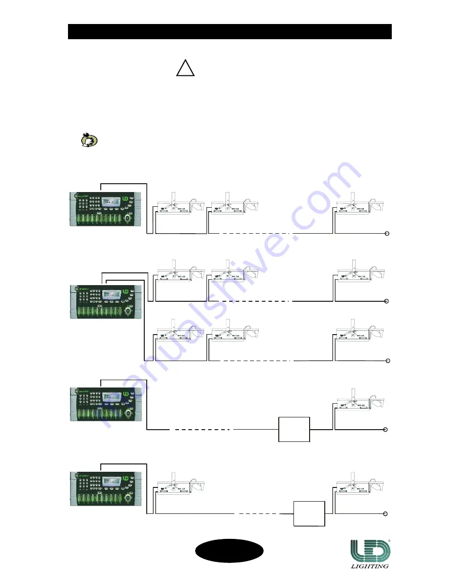
LINE TERMINAL

PROJECTOR

LINE TERMINAL

DMX CONTROLLER

DMX CONTROLLER

LINE TERMINAL

LINE TERMINAL

LINE TERMINAL

9


DMX LINE TERMINAL

Do not connect or wrongly connect the DMX line terminal is probably the most common cause of a defective
functioning of a DMX line.
The DMX line terminal is a resistance placed between the two data pin 2 and 3 at the end of the line.
The terminal resistance should ideally have the same value of the impedance of the DMX connecting cable.
It is recommended, for all DMX system, to insert the line terminal into the DMX output connector of the last
connected projector .

EXAMPLES OF CONNECTIONS: DMX CONTROLLER - PROJECTOR

DMX CONTROLLER

DMX SIGNAL CONNECTION

DMX SIGNAL CONNECTION

DMX SIGNAL CONNECTION

DMX SIGNAL CONNECTION

DMX SIGNAL CONNECTION

It is suggested to use a DMX line terminal with a resistance value of 100/120 Ohm.
We supply, on request, a DMX line terminal with a resistance value of 120 Ohm.

IMPORTANT

!

PROJECTOR

PROJECTOR

PROJECTOR

PROJECTOR

PROJECTOR

LAST PROJECTOR

LINE < 100mt. (with microphonic or audio cable)

LINE < 100mt. (with microphonic or audio cable)

PROJECTOR

LAST PROJECTOR

LAST PROJECTOR

LAST PROJECTOR

LAST PROJECTOR

SIGNAL

AMPLIFIER

DMX 1 output line

DMX 2 output line

EXAMPLE 1

Controller-projector connection with

only one DMX 512 OUTPUT LINE

SIGNAL

AMPLIFIER

EXAMPLE 2

Controller-projector connection with

two or more DMX 512 OUTPUT LINE

EXAMPLE 3

Controller-projector connection with only one

DMX 512 OUTPUT LINE long more than 150mt.

EXAMPLE 4

Controller-projector connection with only one

DMX 512 OUTPUT LINE long more than 150mt.

LINE > 150mt. (with microphonic or data transmission cable)

LINE > 150mt. (with microphonic or data transmission cable)

LINE < 100mt. (with microphonic or audio cable)

SC-12/R

CODE 991247

Summary of Contents for SC-12/R

Page 1: ...User s manual product code 991247 ...

Page 2: ... FOCUS AND MIRROR ADJUSTMENT page 8 GOBOS REPLACEMENT page 8 DMX SIGNAL CONNECTION page 9 CONFIGURATION AND CONTROLS page 10 SWITCH OPTIONS page 11 DMX CHANNELS FUNCTIONS page 12 TROUBLESHOOTING page 13 TABLE 1 GENERAL PROBLEMS page 13 TABLE 2 PROBLEMS TO THE CONNECTION DATA LINK page 14 MOTORS PC BOARD page 15 MAINTENANCE page 18 APPENDIX A 8 CHANNELS CONFIGURATION page 18 INDEX INDEX INDEX INDEX...

Page 3: ... connections so to easily use it INTRODUCTION INTRODUCTION INTRODUCTION INTRODUCTION INTRODUCTION All the sections of this manual have been studied to make as easy and complete as possible the use of the SC 12 R To make the manual more clear and easy to consult we have used the following symbols and conventions very important warnings to be read with the maximum attention important parts of the te...

Page 4: ...rojector use a safety chain 2 To avoid explosion risks open the projector only after 5 minutes after the lamp is off 3 The temperature of the projector can reach high levels Wait for almost 5 minutes before operating on it 4 Replace the Lamp if it is damaged or deformed by the heat PROTECTION AGAINST UV RADIATIONS HAZARDS 1 Do not start on the projector without the protecting screen or if the lens...

Page 5: ...l e e h w r u o l o c e h t f o d e e p s n o i t a t o r e h t e t a l u g e r o t e l b i s s o p s i t I S O B O G G N I T A T O R S O B O G G N I T A T O R S O B O G G N I T A T O R S O B O G G N I T A T O R S O B O G G N I T A T O R 7 e g a p a 3 g i f E T I H W e l b a e g n a h c r e t n i l l a S O B O G G N I T A T O R 6 t c e f f e w o b n i a r l e e h w o b o g e h t f o d e e p s n o ...

Page 6: ...low these instructions 1 Unscrew the knobs placed at the both sides of the unit fig 1 2 Orientate the unit in the preferred position 3 Screw the above said knobs Once finished make sure that the unit is correctly fixed and stable Always make sure that you are using a safety chain Do not install the unit outdoor directly exposed to rain or moisture To avoid installing the projector close to heat so...

Page 7: ...oisture 9 Before connecting the projector to the main power supply make sure that the working voltage and frequency correspond to the values indicated on the label fig 2 The SC 12 R is supplied to work at a working voltage of 230V 50Hz 60Hz on request 10A For being supplied with a voltage of 100 120V it is absolutely necessary an auto transformer with the following characteristics Output voltage 2...

Page 8: ...y cause interruptions to the thermic and electrical conduction 5 Undo the two lateral bushes of the new lamp and insert it in the lamp holder positioning up the bulb protuberance fasten the lamp bushes Avoid touching the new lamp with the nude hands in case it accidentally happens clean the bulb with the proper tissue given with the replacement lamp 6 Make sure the spring clip is back in its place...

Page 9: ...k the two knobs It is also possible to remove the mirror housing To do the above mentioned operation it is necessary to unscrew the focus regulation knob loosen the two mirror regulation knobs disconnect the connector unscrewing the appropriate bush fig 4 ATTENTION disconnect connect the connector only when the projector is Off take off the mirror housing screw the focus regulation knob To assembl...

Page 10: ...N It is suggested to use a DMX line terminal with a resistance value of 100 120 Ohm We supply on request a DMX line terminal with a resistance value of 120 Ohm IMPORTANT PROJECTOR PROJECTOR PROJECTOR PROJECTOR PROJECTOR LAST PROJECTOR LINE 100mt with microphonic or audio cable LINE 100mt with microphonic or audio cable PROJECTOR LAST PROJECTOR LAST PROJECTOR LAST PROJECTOR LAST PROJECTOR SIGNAL AM...

Page 11: ... START ADDRESS to fix the DMX addresses OPTIONS to activate not activate optional functions DMX SIGNAL CONNECTION DMX SIGNAL CONNECTION DMX SIGNAL CONNECTION DMX SIGNAL CONNECTION DMX SIGNAL CONNECTION DMX SIGNAL CONNECTION The DMX signal connection to the SC 12 R must be done through the input signal connectors XLR 5 pins placed on the rear panel of the projector fig 5 The nomenclature of the pin...

Page 12: ...light DIP SW 3 beam OFF to change gobos ROTATING GOBO wheel not obscuring the light beam REVERSE PAN TILT CHANNELS ON to reverse the PAN TILT channels DIP SW 4 OFF normal REVERSE PAN ON to reverse the PAN movement DIP SW 5 OFF normal REVERSE TILT ON to reverse the TILT movement DIP SW 6 OFF normal RESERVED FOR CHECKING ON to execute the projector setting DIP SW 7 OFF normal TEST ON to execute the ...

Page 13: ... I D W S P I D W S P I D W S P I D W S P I D 8 W S P I D W S P I D W S P I D W S P I D W S P I D 1 1 1 1 1 1 2 2 2 2 2 4 4 4 4 4 8 8 8 8 8 6 16 16 16 16 1 2 32 32 32 32 3 4 64 64 64 64 6 8 2 1 8 2 1 8 2 1 8 2 1 8 2 1 6 5 2 6 5 2 6 5 2 6 5 2 6 5 2 1 N R O T C E J O R P 8 1 N ON ON ON ON O F F O F F O F F O F F O F F O F F O F F O F F O 2 N R O T C E J O R P 6 1 9 N ON ON ON ON O F F O F F O N ON ON...

Page 14: ... t a r g f f o r o t c e t o r p c i m r e h t s k r o w r o t c e j o r p e h T s k r o w r o t c e j o r p e h T s k r o w r o t c e j o r p e h T s k r o w r o t c e j o r p e h T s k r o w r o t c e j o r p e h T e h t t u b y l t c e r r o c n r u t t o n s e o d p m a l y l t n e t t i m r e t n i r o n o f f o s n r u t p m a l e v i t c e f e D p m a l e h t k c e h C s u t a t s p m a l e...

Page 15: ... h t e c a l p e R e l b a c e h t f o 3 d n a 2 n i P e h t f o r o t c e n n o c e r a e l b a c g n i t c e n n o c d e t r e v n i d e t s e t y d a e r l a n a e s U t c e n n o c d n a e l b a c r e p r o t c e j o r p e n o e h t l i t n u e m i t s i e l b a c e v i t c e f e d t u o d n u o f n i e l b a c g n i t c e n n o C t i u c r i c t r o h s d e t s e t y d a e r l a n a e s U t c...

Page 16: ...R wheels 2 connect the cable of the ROTATING GOBO wheel to the connector of the COLOUR wheel 3 start on the projector 3a if the motor of the ROTATING GOBO wheel works properly it is necessary to replace U16 PBL3771 3b if the ROTATING GOBO motor still does not work it is necessary to carefully check it so as all the connections circuits cable and connectors TILT PAN DMX INPUT TROUBLESHOO TROUBLESHO...

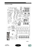
Page 17: ...1 6 ELECTRICAL SCHEMES MS06 TROUBLESHOO TROUBLESHOO TROUBLESHOO TROUBLESHOO TROUBLESHOOTING TING TING TING TING SC 12 R CODE 991247 ...

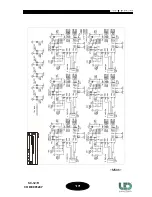
Page 18: ...1 7 MS06 TROUBLESHOO TROUBLESHOO TROUBLESHOO TROUBLESHOO TROUBLESHOOTING TING TING TING TING SC 12 R CODE 991247 ...

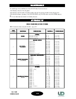
Page 19: ... D R U O L O C E R U O L O C F R U O L O C G R U O L O C H R U O L O C I R U O L O C L R U O L O C d e e p s 6 1 W O B N I A R 5 1 0 0 0 0 1 3 0 6 1 0 7 4 0 2 3 0 3 6 0 8 4 0 9 7 0 4 6 0 5 9 0 0 8 0 1 1 1 6 9 0 7 2 1 2 1 1 3 4 1 8 2 1 9 5 1 4 4 1 5 5 2 0 6 1 6 0 0 0 2 1 7 0 8 1 3 1 5 2 9 1 1 3 6 2 7 3 2 3 3 4 8 3 0 5 4 4 6 5 1 5 2 6 7 5 0 0 1 3 6 3 S O B O G G N I T A T O R S O B O G G N I T A T O...

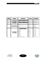
Page 20: ... S R A O C T I B 8 G N I N O I T I S O P E S R A O C T I B 8 G N I N O I T I S O P E S R A O C T I B 8 G N I N O I T I S O P E S R A O C T I B 8 G N I N O I T I S O P E S R A O C 0 4 5 5 2 0 0 0 0 0 1 0 0 7 N O I T A T O R S O B O G N O I T A T O R S O B O G N O I T A T O R S O B O G N O I T A T O R S O B O G N O I T A T O R S O B O G P O T S N O I T A T O R T H G I R O T T F E L P O T S N O I T A...

Page 21: ...NO NO NO NO NOTES TES TES TES TES 20 SC 12 R CODE 991247 ...

Page 22: ...g for LED and they could be changed at any time without notice LED it is not responsible for any inconvenience caused by an improper or different use of the unit respect to the one for what it has been made LED s r l ZONA P I P Contrada Pozzillo Viale Saponaro D Lotto G N 8 70016 Noicattaro BA Italy Tel 39 080 9906090 Fax 39 080 9906092 3 Web Site www ledsrl it e mail info ledsrl it Rev 12 2005 ...

Reviews: