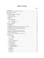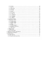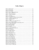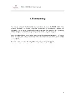
MULTIDETEK 2 User’s manual
10
DID
The principle of the DID is based on the ionization of the molecules. The detector has its
discharge area that is made of quartz to create an ionization zone and it’s used to create
photons. The photons are used to ionize the sample molecules and then create ions that are
captured by electrodes, when sample is introduced in the detector. The DID is a universal
detector offering multiple applications.
5.2 Analyzer application
The MultiDetek2 is designed to be used
for the impurity and sampling details on the
specification sheet of the instrument only
. Using this instrument with any other type of
gases can cause damage to the analyzer. Please refer to the document “Operating
Parameters” that comes with the unit.
The MultiDetek2 is not an instrument to be used in hazardous area.
5.3 Start-up
All LDetek products are properly packed in a cardboard box and all instruments come with
an associate document name “Operating parameters”. Refer to the steps below to ensure
the proper start-up for this unit.
1.
Unpack the instrument carefully from the box and inspect it to be sure it is in good
condition and hasn’t been damaged during shipping.
2.
Find the documents of the instrument, USB key, fuse kit and power cables that are all
included in every box.
3.
The unit can be installed on a table or mounted in a rack. If it is mounted in a rack,
refer to section 8.0 for drawings to evaluate the good panel cut out and space required.
4.
Once the unit is in place, it is required to install and purge the carrier gas lines prior to
connect them to the MultiDetek2. The carrier gas type and pressure to respect are
mentioned in the document “Operating Parameters”. For gas lines connections, refer to
the tubing schematic that comes with the unit.
5.
The LDP1000 gas purifier has to be purged. Refer to the LDP1000 installation
procedure to ensure that it is properly installed.
Summary of Contents for MultiDetek2
Page 1: ......
Page 2: ......
Page 3: ...MultiDetek 2 Trace impurities analyzer USER S MANUAL V3 9 Printed in Canada Copyright 2016 ...
Page 13: ...MULTIDETEK 2 User s manual 6 ...
Page 14: ...MULTIDETEK 2 User s manual 7 ...
Page 26: ...MULTIDETEK 2 User s manual 19 Figure 6 Typical Installation ...
Page 28: ...MULTIDETEK 2 User s manual 21 Figure 7 Same source actuation ...
Page 29: ...MULTIDETEK 2 User s manual 22 Figure 8 2 sources actuation ...
Page 31: ...MULTIDETEK 2 User s manual 24 Figure 9 O2 doping ...
Page 73: ...MULTIDETEK 2 User s manual 66 8 0 Backpanel terminal identification ...
Page 75: ...MULTIDETEK 2 User s manual 68 9 0 Drawings Schematics ...
Page 76: ...MULTIDETEK 2 User s manual 69 Unit dimensions and cut out dimensions ...
Page 82: ...MULTIDETEK 2 User s manual 75 MotherBoard PCB ...
Page 83: ...MULTIDETEK 2 User s manual 76 Motherboard PCB electrical connections ...
Page 87: ...74 ...
Page 88: ...75 ...
Page 89: ......
Page 90: ......


