MULTIDETEK 2 User’s manual
23
5.5.3 O2 doping
Figure 6 shows a typical installation that requires O2 doping. This feature is used to keep
our system saturated with Oxygen. In chromatography, it is well known that oxygen is
adsorbed by the Molecular Sieve and also by the porous polymer type columns used for
separating and measuring trace oxygen. Even if a good column activation is performed at
the beginning, over time the oxygen will slowly desorb from the column and the column
will start to adsorb the oxygen content coming from the volume of sample gas injected.
This phenomenon has a big impact on the analysis accuracy for measuring Oxygen at
ppm/ppb due to a part of the sample staying inside the columns. It generally results in a
loss of the ppb/ppm peak of Oxygen even on the span calibration gas. By adding an Oxygen
doping gas, the active sites inside the columns are permanently filled with Oxygen. It
stabilizes the system and ensures a good reproducibility and accuracy resulting in better
sensitivity.
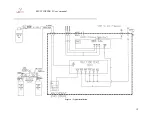
Figure 9 shows a typical example of a GC plumbing diagram having an O2 doping option.
Valve 10 is a 2 streams selector that switches between the sample gas and the doping gas.
The doping gas must be connected to a certified gas bottle containing a known
concentration between 100-1000ppm O2 in a balance gas being the same as the carrier gas.
The pressure of that said bottle must be set at a value between 10-30psig. Depending on
the GC application, the flow consumption of the doping gas will be as low as 100sccm for
a period varying from 2-7 minutes per cycle depending on the GC configuration. Such a
bottle can last for a long period before needing to be replaced.
Valve 10 is switching to the doping gas during an analysis cycle at a moment following the
elution of the measured impurities in the channel used to measure the trace oxygen.
Generally, the sampling loop of this channel is the first to be injected to ensure that the
oxygen doping gas can be injected as quickly as possible, eventually being flushed out of
the system rapidly. This is the reason why the time that the doping gas is in the loops varies
from 2-7 minutes. It is application dependent, but we always try to minimize it during our
tuning process. By the time the analysis of the other impurities is progressing, the oxygen
doping gas is flowing through the columns of interest for saturating them with oxygen. By
going this way, automatically every cycle, the system stays in good condition for measuring
oxygen.
Summary of Contents for MultiDetek2
Page 1: ......
Page 2: ......
Page 3: ...MultiDetek 2 Trace impurities analyzer USER S MANUAL V3 9 Printed in Canada Copyright 2016 ...
Page 13: ...MULTIDETEK 2 User s manual 6 ...
Page 14: ...MULTIDETEK 2 User s manual 7 ...
Page 26: ...MULTIDETEK 2 User s manual 19 Figure 6 Typical Installation ...
Page 28: ...MULTIDETEK 2 User s manual 21 Figure 7 Same source actuation ...
Page 29: ...MULTIDETEK 2 User s manual 22 Figure 8 2 sources actuation ...
Page 31: ...MULTIDETEK 2 User s manual 24 Figure 9 O2 doping ...
Page 73: ...MULTIDETEK 2 User s manual 66 8 0 Backpanel terminal identification ...
Page 75: ...MULTIDETEK 2 User s manual 68 9 0 Drawings Schematics ...
Page 76: ...MULTIDETEK 2 User s manual 69 Unit dimensions and cut out dimensions ...
Page 82: ...MULTIDETEK 2 User s manual 75 MotherBoard PCB ...
Page 83: ...MULTIDETEK 2 User s manual 76 Motherboard PCB electrical connections ...
Page 87: ...74 ...
Page 88: ...75 ...
Page 89: ......
Page 90: ......


