MULTIDETEK 2 User’s manual
53
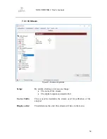
7.3.1.9 4-20mA
Figure 40: 4-20mA settings menu
Setup:
By double-clicking on it you can change:
•
The name of the 4-20mA
•
The analog output associated with it
Measured 4mA:
The current measured during the calibration should be put there.
By double clicking on the field, the output will be set to 4mA.
Measured 20mA:
The current measured during the calibration should be put there
Calibration Test:
To force the selected 4-20mA output at the desired value
Display Order:
This determine the order this 4-20ma out will have in the menu.
Summary of Contents for MultiDetek2
Page 1: ......
Page 2: ......
Page 3: ...MultiDetek 2 Trace impurities analyzer USER S MANUAL V3 9 Printed in Canada Copyright 2016 ...
Page 13: ...MULTIDETEK 2 User s manual 6 ...
Page 14: ...MULTIDETEK 2 User s manual 7 ...
Page 26: ...MULTIDETEK 2 User s manual 19 Figure 6 Typical Installation ...
Page 28: ...MULTIDETEK 2 User s manual 21 Figure 7 Same source actuation ...
Page 29: ...MULTIDETEK 2 User s manual 22 Figure 8 2 sources actuation ...
Page 31: ...MULTIDETEK 2 User s manual 24 Figure 9 O2 doping ...
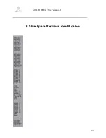
Page 73: ...MULTIDETEK 2 User s manual 66 8 0 Backpanel terminal identification ...
Page 75: ...MULTIDETEK 2 User s manual 68 9 0 Drawings Schematics ...
Page 76: ...MULTIDETEK 2 User s manual 69 Unit dimensions and cut out dimensions ...
Page 82: ...MULTIDETEK 2 User s manual 75 MotherBoard PCB ...
Page 83: ...MULTIDETEK 2 User s manual 76 Motherboard PCB electrical connections ...
Page 87: ...74 ...
Page 88: ...75 ...
Page 89: ......
Page 90: ......


