MULTIDETEK 2 User’s manual
58
7.3.1.14 QMA
Figure 45: QMA setting menu
Enable:
Peak:
Enable or disable the QMA
Assign the QMA to peak.
Valve:
Assign a valve to the QMA. The selected valve will control the
sensor.
Oven:
Sample LDepc:
Calib LDepc:
Analog input:
Nb data average:
Use Area:
Assign an oven to the QMA. The selected oven will control the
sensor temperature.
Assign the LDepc that will control the sample flow.
Assign the LDepc that will control the dry gas flow for QMA
calibration.
Select the analog input used for QMA. It as to be created as “Single
Detector” first.
Choose the number of points that will be used for averaging.
Chose between the calculation algorithms. The Area mode will
calculate the area of a complete cycle. The Delta mode will
calculate the height of the signal during each cycle.
Summary of Contents for MultiDetek2
Page 1: ......
Page 2: ......
Page 3: ...MultiDetek 2 Trace impurities analyzer USER S MANUAL V3 9 Printed in Canada Copyright 2016 ...
Page 13: ...MULTIDETEK 2 User s manual 6 ...
Page 14: ...MULTIDETEK 2 User s manual 7 ...
Page 26: ...MULTIDETEK 2 User s manual 19 Figure 6 Typical Installation ...
Page 28: ...MULTIDETEK 2 User s manual 21 Figure 7 Same source actuation ...
Page 29: ...MULTIDETEK 2 User s manual 22 Figure 8 2 sources actuation ...
Page 31: ...MULTIDETEK 2 User s manual 24 Figure 9 O2 doping ...
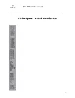
Page 73: ...MULTIDETEK 2 User s manual 66 8 0 Backpanel terminal identification ...
Page 75: ...MULTIDETEK 2 User s manual 68 9 0 Drawings Schematics ...
Page 76: ...MULTIDETEK 2 User s manual 69 Unit dimensions and cut out dimensions ...
Page 82: ...MULTIDETEK 2 User s manual 75 MotherBoard PCB ...
Page 83: ...MULTIDETEK 2 User s manual 76 Motherboard PCB electrical connections ...
Page 87: ...74 ...
Page 88: ...75 ...
Page 89: ......
Page 90: ......


