MULTIDETEK 2 User’s manual
62
7.5.3 Digital output
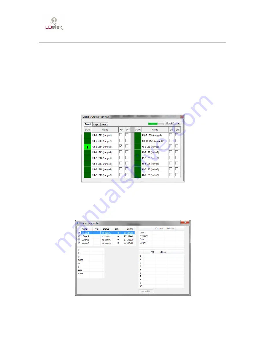
This menu displays all digital output in the MultiDetek2 with their actual value. If the
square is grey, the state of the output is unknown (probably a communication problem), if
the square is dark green, the output is OFF, if the square is light green, the output is ON.
You can force any output at OFF or ON. When a state is forced, an “F” is displayed in
the square.
The progress bar in the corner shows the refreshing rate.
Figure 49: Digital output window
7.5.4 LDepc
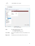
This menu displays the communication status, the actual flow, the actual pressure, the
flow table and the PID of the LDepc.
Figure 50: LDepc diagnostic window
Summary of Contents for MultiDetek2
Page 1: ......
Page 2: ......
Page 3: ...MultiDetek 2 Trace impurities analyzer USER S MANUAL V3 9 Printed in Canada Copyright 2016 ...
Page 13: ...MULTIDETEK 2 User s manual 6 ...
Page 14: ...MULTIDETEK 2 User s manual 7 ...
Page 26: ...MULTIDETEK 2 User s manual 19 Figure 6 Typical Installation ...
Page 28: ...MULTIDETEK 2 User s manual 21 Figure 7 Same source actuation ...
Page 29: ...MULTIDETEK 2 User s manual 22 Figure 8 2 sources actuation ...
Page 31: ...MULTIDETEK 2 User s manual 24 Figure 9 O2 doping ...
Page 73: ...MULTIDETEK 2 User s manual 66 8 0 Backpanel terminal identification ...
Page 75: ...MULTIDETEK 2 User s manual 68 9 0 Drawings Schematics ...
Page 76: ...MULTIDETEK 2 User s manual 69 Unit dimensions and cut out dimensions ...
Page 82: ...MULTIDETEK 2 User s manual 75 MotherBoard PCB ...
Page 83: ...MULTIDETEK 2 User s manual 76 Motherboard PCB electrical connections ...
Page 87: ...74 ...
Page 88: ...75 ...
Page 89: ......
Page 90: ......


