background image


Specifications & Ratings 

To ensure proper operation and to avoid equipment failure, the following specifications 

and ratings must be observed: 


Frequency Range: 1.8 to 54 MHz 
Maximum Input Power: 125W PEP (CW / SSB / AM), 30W (Digital / RTTY / FM) 
Input Impedance: 50 Ω  
Tuning Range: 10:1 SWR 
Memories: 2000 
Retune Time: < 1.0 s. 
Voltage: 13.8 VDC + 15% 
Current Draw: 500 mA tuning, 20 mA idle 
Size: 6.3”x6.3”x1.5” (160x160x40mm) 
Weight: 1.5 lbs (680 g) 
 
Compatible Transceivers 
The Z-100A is designed to be used with any Icom 100-watt transceiver that supports the AH-
3 or AH-4 Icom antenna tuners. Currently, this includes: 

IC-706


IC-718 (select AH-4)


IC-746


IC-7000 

NOTE: If using with an IC-718 select AH-4 mode. See the IC-718 owner’s manual for details. 

The radio interface cable supplied is 14” long. If the Z-100A is positioned farther from the 
transceiver, a custom cable can be constructed.  This can be accomplished in two ways: Cut 
the supplied cable and solder a jumper wire between all the connections, or purchase new 
connectors and cable to construct a custom-length interface cable from scratch. 

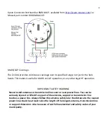
The 4-pin AH-4 interface connector is Molex part number 03-09-2042, available from 
several online component vendors, such as DigiKey

1

 and Mouser

2

. The connector also 

requires four pins, Molex part number 02-09-2103. The 6-pin Z-100A interface connector is 


1


http://www.digikey.com/


1


http://www.mouser.com


2

 For a very complete treatment of this subject, see any edition of the ARRL Handbook for Radio Communications (previously the Handbook For Radio 

Amateurs).


Summary of Contents for Z-100A

Page 1: ...LDG Electronics Z 100A Antenna Tuner For HF transceivers LDG Electronics Inc 1445 Parran Rd St Leonard MD 20685...

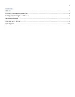
Page 2: ...1 Contents Welcome 2 Introducing the Z 100A Automatic Tuner 4 Installing and Connecting the Z 100A tuner 5 Specifications Ratings 7 Operating your Z 100A tuner 9 Operating Hints 12...

Page 3: ...es not warranty against product damage or abuse This means that a product failure as determined by LDG to be caused by the customer or by other natural calamity e g lightning is not covered under the...

Page 4: ...airs can take six to eight weeks but are usually faster The most recent information is found at the LDG Customer Support Center Send your carefully packaged unit with the Repair Form to LDG Electronic...

Page 5: ...tion in mind this tuner is powered directly by the interface on the back of the radio no need to worry about any additional power connections Also a single push button switch is all that s needed to c...

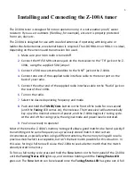
Page 6: ...ect the desired operating frequency and mode 8 Push and hold the TUNER CALL button on the front of the radio for one second until the Tuning LED comes on then release The transceiver will automaticall...

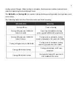
Page 7: ...tion Meaning Tuning LED on Tuner is tuning Tuning LED goes out SWR LED comes on solid Tuner has completed a tuning cycle a good SWR match was found Tuning LED goes out SWR LED blinks 5 times Tuning cy...

Page 8: ...select AH 4 mode See the IC 718 owner s manual for details The radio interface cable supplied is 14 long If the Z 100A is positioned farther from the transceiver a custom cable can be constructed This...

Page 9: ...gal HF operation IMPORTANT SAFETY WARNING Never install antennas or transmission lines over or near power lines You can be seriously injured or killed if any part of the antenna support or transmissio...

Page 10: ...s hold the tuned configuration indefinitely even when DC power is completely removed Tuning memories are stored in FLASH memory The Z 100A has 2 000 frequency memories When tuning on or near a previou...

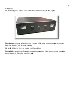
Page 11: ...Button Initiates either a memory tune or a full tune and also toggles the tuner between active and bypass modes SWR LED Lights or blinks to indicate SWR condition Tuning LED Lights to give feedback on...

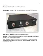
Page 12: ...wing nut Connect to antenna system ground TX connector Connect the 50 coax jumper cable from this standard SO 239 connector to the ANT jack on the rear of the transceiver Radio connector This 6 pin m...

Page 13: ...a blinking icon while tuning and a solid icon when tuning is complete This icon disappears when the tuner is bypassed and blinks if a tuning cycle failed to find a good match Other ICOM transceivers...

Reviews: