PDU6M MANUAL V0.1
10
Luci della Ribalta srl - Via Berna 14, Z.I. Bosco dell’Irta, 46042 Castel Goffredo MN, Italy
tel. +39 0376 771 777 - fax +39 0376 772 140 - email info@ldr.it - web www.ldr.it
Page 08 of 22
ENGLISH
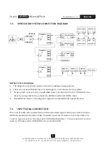
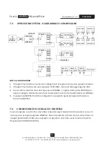
The signal input to the PDU6M can be transmitted from one of the following types of equipment:
- a controller (such as UDM-1 in the system diagram)
- an amplifier (such as IDAxxM in the system diagram)
- the previous PDU6M (from through port)
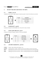
The power and output signal (XLR4M and XLR4F) supply respectively power and signal to the
colour scrollers. Please use
XLR4M and XLR4MF of the cable will be
connected to colour scrollers in a loop.
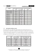
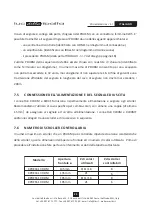
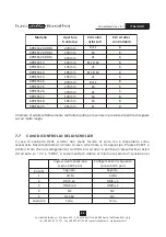
The number of colour scrollers that one PDU6M can control depends on the specifications of the
colour scroller, such as aperture size and gel string type (number of colour gels). Before starting
connection please refer to the below chart to double check how many scrollers each PDU can
control.
The actual number of controlled units could however vary from what below indicated
due to possible loss of power through long cables.
The last PDU6M in the chain should be terminated with a terminating resistor.
The number of PDU6M in one PDU6M chain should never exceed 32 sets, ideally not exceed 16
sets. To ensure a reliable transmission, the length of signal control cable should not exceed 200m.
7.5
POWER AND OUTPUT SIGNAL CONNECTION
7.6
CONTROLLABLE UNITS
dedicated colour scroller cable, including one pair twist cable for signal
and one pair for power cable (above 1.5mm ). The
2
Model
Front aperture
size ø
# of colour
frames
# of controllable
units
XPRESS 13 RDM
XPRESS 13 RDM
XPRESS 19 RDM
XPRESS 19 RDM
135mm
135mm
195mm
195mm
8/11/16
8/11/16
21
21
8
8
6
6


