background image

SAFETY PRECAUTIONS

SECTION 1

OPERATION
GENERAL

1. It is the operator’s responsibility to ensure that

operation of the unit is in accordance with the
guidelines contained in the Operator’s manual and
in accordance with all applicable codes including
Occupational Safety and Health Act (OSHA) and
American National Standards Institute (ANSI) reg-
ulations.

2. Do not attempt to operate this equipment without

proper training.

3. Move the vehicle as slowly as possible without

stalling when traveling in reverse.

4. Always make sure the area behind the unit  is clear

before  traveling in reverse.

5. Do not travel in reverse for distances greater than

those dictated by local ordinances. If reverse trav-
el exceeds 10 feet, use a “spotter” or move the
vehicle in 10 foot increments only, and then check
to make sure the area behind the unit is clear
between increments.

6. Do not attempt to dislodge any material above

waist level unless wearing eye protection such as
“approved” side shielded safety glasses or a full
face shield.

7. Never use the unit to push or tow another vehicle.

8. Never unload uphill or against a pile of refuse or

into the bank of a hill.

9. Never place head, body, fingers or any limbs into a

scissors point or pinch point on the equipment.

10. Before operating the vehicle the driver must be

thoroughly familiar with the employer’s safety pro-
gram concerning traffic rules, warning devices and
hand signals.

11. Know where to get assistance in the event of an

emergency.

12. Know your machine. Know the location and func-

tion of all controls, gauges, instruments and pro-
tective devices.

13. Wear your seat belt.

14. Start the engine following the manufacturer’s rec-

ommended procedure.

15. Always set the parking brake before leaving the

cab.

16. Turn on appropriate warning lights, put on a safety

vest, protective glasses and protective shoes.

17. All service opening covers and access doors must

be maintained and latched in place while operating
equipment.

18. Ensure all co-workers are in view before operating

or moving any controls or the unit.

19. Ensure that there is sufficient overhead clearance

before operating the unit.

20. Ride only in the cab or on riding platforms

designed for that purpose. Riding steps shall not
be used when speeds are expected to exceed 10
mph or when distance traveled without stopping
will exceed 

2

10

of one mile. Do not mount or dis-

mount riding step when vehicle is in motion.

21. Never allow anyone to ride on the steps when the

vehicle is backing up.

22. Stop the vehicle immediately if warning lights for

the TAILGATE AJAR system come on.

23. Never use controls or hoses for hand holds when

mounting or dismounting. Controls and hoses are
movable. They do not provide proper support and
may cause accidental equipment movement.

24. Make sure the backup alarm is working properly.

25. Always ensure that all persons are clear before

raising or lowering the tailgate. It is the operator's
responsibility to warn all persons not to stand or
cross under a raised tailgate.

26. Do not move the vehicle with the tailgate raised

except during unloading and then only as neces-
sary to clear the load before lowering.

27. Stand clear when the tailgate is being raised or

lowered and during the unloading cycle. If it is nec-
essary to manually clear debris from the hopper,
use a long metal probe and DO NOT stand under
the tailgate.

28. Never load the hopper above the loading sill.

29. Never allow material to extend outside of the hop-

per when packing.

30. Allow the packer panel control lever and carrier

panel control lever to shift automatically.

31. To avoid possible bodily injury or equipment dam-

age, lower the tailgate slowly.

32. Never enter the body unless the pushout panel

clamp or the telescopic ejection system cylinder is
released, PTO disengaged and ignition key
removed and placed in your pocket.

33. Do not attempt to load refuse into the hopper after

1-3

Summary of Contents for 2R-II

Page 1: ...2RII PACKMASTER OPERATORS MANUAL Over Serial Number 16000 BUILDING THE BEST...

Page 2: ......

Page 3: ...TS LIMITED WAR RANTY OF REPLACEMENT HEREIN NO OTHER PERSON FIRM OR CORPORATION CAN BIND THE COMPANY TOANY WARRANTY OTHER THAN HEREINABOVE STATED To validate the new unit warranty an authorized Leach D...

Page 4: ...nual was produced with the intention of providing clear concise instructions for the proper operation maintenance and service of your 2RII refuse packer It was produced with the latest information ava...

Page 5: ...6 Basic Operation 2 7 Attach 2 7 Dump 2 7 Disconnect 2 7 SECTION 3 OPERATION General 3 1 Description of Operating Controls 3 1 Location Of Operating Controls 3 2 Compaction Cycle Operation 3 5 Operati...

Page 6: ...liance to these safety alerts combined with common sense operations are important accident pre vention measures The word NOTE is also used throughout the manual It precedes information that provides s...

Page 7: ...moved and using a non reusable fasten ing device place a sign on the steering wheel indicating the unit is inoperative 4 Proper servicing requires specialized tools and pro cedures Service must be per...

Page 8: ...All service opening covers and access doors must be maintained and latched in place while operating equipment 18 Ensure all co workers are in view before operating or moving any controls or the unit 1...

Page 9: ...ttachment point while taking up slack 46 Take up excess cable slack before moving the vehi cle 47 Check overhead clearance before dumping a con tainer 48 Do not move the vehicle with a container attac...

Page 10: ...a light source 4 Never load ashes or other materials which might be smoldering These materials could ignite refuse in the packer body HOUSEKEEPING Good housekeeping habits are a major factor in acci d...

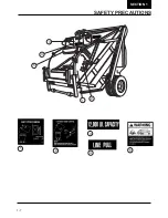
Page 11: ...1 6 SAFETY PRECAUTIONS SECTION 1 1 4 2 5 6 3 7 8 9 10 7 7 9 1 8 4 5 2 6 10 1 3 1 6...

Page 12: ...SAFETY PRECAUTIONS SECTION 1 2 1 3 4 5 1 2 3 4 5 1 7...

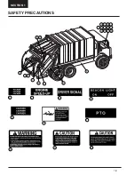
Page 13: ...SAFETY PRECAUTIONS SECTION 1 1 1 2 3 11 14 23 17 5 12 6 4 7 9 10 13 15 16 18 19 8 20 21 22 2 3 4 5 6 7 8 9 10 1 8...

Page 14: ...SAFETY PRECAUTIONS SECTION 1 11 12 13 14 15 16 17 18 19 20 21 22 23 1 9...

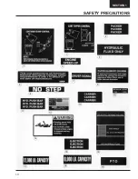
Page 15: ...44 6 12 44 20 30 43 7 28 5 8 15 4 16 39 21 34 4 5 6 7 16 8 12 15 20 21 28 43 30 44 39 SECTION 1 SAFETY PRECAUTIONS 1 10...

Page 16: ...SAFETY PRECAUTIONS SECTION 1 1 11...

Page 17: ......

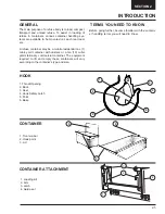
Page 18: ...INTRODUCTION SECTION 2 TERMS YOU WILL NEED TO KNOW TAILGATE ASSEMBLY HOPPER LOADING EDGE HYDRAULIC TANK PUSHOUT PANEL CARRIER PANEL PACKER PANEL 2 1...

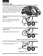
Page 19: ...tion of the 2RII Packmaster and become familiar with the terms you will need to know LOADING Refuse is first loaded into the hopper of the tailgate assembly The carrier and packer panels which sweep u...

Page 20: ...g for a large carrying capacity On units with the standard clamp pushout system the operator must manually release the pushout panel clamping system to allow movement of the pushout panel Once the bod...

Page 21: ...container arms when properly latched together with the guide ears will secure the container to the packer Only containers that meet the American National Standards Institue ANSI regulations should be...

Page 22: ...ential one 1 cubic yard container with casters or a ten 10 cubic yard stationary commercial container The equipment required to lift and empty these containers will vary according to the container s t...

Page 23: ...TAINER LIFTING CYLINDER CLC 1 Control lever 2 Engine speed up button 3 Roller guide 4 5 6 Cable 7 Lifting cylinder assembly Container attachment Stop bar Lid guard CONTAINER PUSH BAR CPB 1 Control lev...

Page 24: ...e con tainer to the rear loader by securing it with the latch arms of the container attachment DUMP A container handling system is used to raise the con tainer and empty the refuse into the hopper of...

Page 25: ......

Page 26: ...CONTROLS The following information is for descriptive purposes only It is not to be misconstrued as operating in structions For operating instructions refer to OP ERATING PROCEDURES later in this sect...

Page 27: ...OPERATION SECTION 3 LOCATION OF OPERATING CONTROLS 1 2 3 8 9 10 11 12 7 4 5 6 7 8 3 2...

Page 28: ...style NOTE The engine speed up system consists of the solenoid ON OFF switch a relay and solenoid air cylinder on electronic engines the relay is wired to the engine ECU A speed up push button and spe...

Page 29: ...ent of the pushout panel Moving the control lever rearward toward the tail gate will move the pushout panel to the rear Moving the controlleverforward towardthecab willmovethepushout panel to the fron...

Page 30: ...cycle NOTE The engine speed up system automatically engages any time the carrier panel lever is shifted COMPACTION CYCLE OPERATION Both the packer panel lever and the carrier panel lever are shifted s...

Page 31: ...location illustration in Section 1 SAFETY of this manual and make sure all decals are in place and readable Replace any decals that are not NOTE A decal kit free of charge is available from your loca...

Page 32: ...erating levers are in the neutral posi tion Check a packer panel lever b Carrier panel lever c Pushout lever d Tailgate lift lever Never operate the 2RII Packmaster with any part of the control system...

Page 33: ...lluminated Never place hands in or near the packer panel dur ing operation 9 With the engine running the speed up solenoid switch ON the PTO engaged and the transmission in neutral and the brakes appl...

Page 34: ...carrier and packer panel movement it should be smooth The panels should stop automatically at the home position 12 Depress the two driver signal push buttons located on both sides of the tialgate to m...

Page 35: ...place and readable 2 Look for any fluid leaks 3 Mounting hardware tight and in place 4 Tailgate clamps closed and tightened 5 Hydraulic fluid reservoir at correct level 6 All operating levers in neut...

Page 36: ...nspect and start the truck as described in the pre operational walk around inspection 2 Engage the Pump PTO control to start the hydraulic pump 3 Place the engine speed up switch in the ON position EN...

Page 37: ...ully extended NOTE On units with a telescopic pushout cylinder the pushout panel is now in position for loading 4 Release the speed up button and pull the pushout lever forward until the pushout cylin...

Page 38: ...y safety restrictions The vehicle should be backed with the latch arms open until the container trunnion bar is between the guide ears and within the latch assembly Center the container on the attachm...

Page 39: ...hown on the instruction decal to raise the container When the cable is tight the speed up button should be depressed and held to provide suf ficient hydraulic power to lift the container The container...

Page 40: ...E LOAD NOTE The compaction cycle can be stopped at any time by moving both the packer panel lever and the carrier panel lever to the center neutral 1 Cycle the packer panel and the carrier panel by mo...

Page 41: ...n the body Also if the packer panel stops short of the home position the carrier panel operating lever may need to be held overridden to allow the refuse to move the pushout panel toward the front of...

Page 42: ...ailgate clamps and swing them out and forward as far as they will go LIFTING THE TAILGATE Stand clear when the tailgate is raised If you need to clean debris from the edges use a pole while standing t...

Page 43: ...ar off to one side With the telescopic circuit the pushout cylinder remains fully extended If the unit is going to travel over one mile empty completely retract the cylinder When packing is about to r...

Page 44: ...packer panel lever and carrier panel lever to place the packer panel in the home position 2 Put all controls in neutral 3 Set parking brake 4 Disengage PTO 5 Shut off engine 6 Shut of solenoid dashboa...

Page 45: ...R SPECIFICATIONS _______ 105557 ALPHA PARTS 2140 3500 _______ 9511134 7 DELTA COLOR SPECIFICATIONS _______ 105556 ALPHA SERVICE 2140 3500 _______ 9603134 2 AL BE SUGGESTED SPECS _______ 105565 BETA PA...

Page 46: ......

Page 47: ...eive a hat by return mail I believe I found an error In the _______________________________________________________________manual Part No ______________________________________________________________...

Page 48: ......

Page 49: ......
Page 50: ...Part Number 105319 2737 Harrison Street Oshkosh Wisconsin 54901 920 231 2770 920 231 2712 FAX Please visit our website www LeachUSA com PRINTED IN U S A April 30 2001 C...

Reviews: