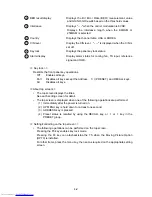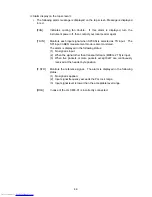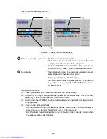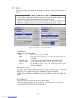
○
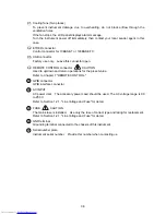
31 Cooling fans (Two places)
To prevent instrument damage due to overheating, do not block airflow through the
ventilation holes.
If the fan stops, the LCD panel displays alarm message.
Turn the instrument power off immediately, then contact your local Leader agent in this
case.
○
32
ETHER connector
Control connector for 10BASE-T or 100BASE-TX.
○
33
USB connector
Factory use only. Leave this connector open.
○
34 REMOTE CONTROL connector
CAUTION
Used to up/down and return operations for the preset value.
Refer to Chapter 7 "REMOTE CONTROL."
35 GPIB
connector
GPIB interface connector.
36 AC
INPUT
AC power inlet. The accessory power coed should be used. The AC voltage range is 90
to 250 V.
Refer to Section 1.2.1, "Line Voltage and Fuse" for detail.
37 FUSE
CAUTION
The mains fuse is installed. Use only the fuse of correct type and rating for replacement.
Refer to Section 1.2.1, "Line Voltage and Fuse" for detail.
38 GND
terminal
Grounding terminal connected to the chassis of this instrument
39 Serial number plate
Instrument serial number. Provide this number when contacting us.
3-5
Get user manuals:

