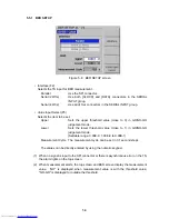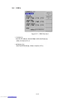
4. LCD PANEL DESCRIPTION
4.1 Turning Power On and Starting Instrument
Connect the accessory power cord between the AC inlet on the rear panel and the mains.
Press the POWER switch to turn power on for starting the system. Whit for about 45
seconds until the top screen (Status screen) is displayed. The setting conditions
immediately before turning power off will be recalled.
4.2 Screen
Description
The screen display consists of the top screen and various setting screens. The
followings describe the typical screens.
<Top Screen>
○
3
○
2
○
5
○
12
○
8
○
7
○
6
○
1
○
4
○
9
○
10
○
11
○
13
Figure 4-1 Top screen
1 Screen title
Indicate the top (Status) screen.
2 Unit information
Indicate the setting parameter of this instrument or OOB.
3 Group
Displays the preset group number.
4 TS signal selection
Selects the TS to be used.
5 Carrier modulation (Current)
Displays the carrier modulation setting status.
6 Channel, frequency
Displays the channel number when the RF signal is set in
channel.
Displays the frequency in units of MHz when the RF
signal is set in frequency.
7 Output level
Displays the output level.
4-1
Get user manuals:


