background image


5


MAINTENANCE OPERATIONS 

14


Maintenance programme 

14


Removing the casing and the bellows 

15


Fuses 

16


Levels 

17


Adjusting the engine speed 

18


CLEANING THE RADIATOR 

18


Elevation (Option) 

18


Air filter 

20


Air filter clogging indicator (optional) 

20


Changing the gearbox oil 

21


Changing the motor oil 

22


Spark plugs 

23


Fan 

24


Fuel filter 

24


Exhaust spring 

25


Alternator belt 

25 


6


FAILURE 

26 


7


SPARE PARTS 

27 


8


MAINTENANCE LOG BOOK 

29 


9


ANNEXE 

30 


10


WARRANTY 

34 


Summary of Contents for 160.30.109

Page 1: ......

Page 2: ... ELEV 600 MM ATTELAGE BOULE I60 30 113 EASY 4000 SUR REMORQUE SANS ELEVATION ATTELAGE BOULE I60 30 112 EASY 4000 SUR SKID ELEVATION 1200 I60 30 111 EASY 4000 SUR SKID ELEVATION 600 I60 30 110 EASY 4000 SUR SKID SANS ELEVATION I60 30 117 EASY 4000 SUR SKID ELEVATION 1200 ROTATION I60 30 115 EASY 4000 SUR SKID ELEVATION 600 ROTATION ...

Page 3: ...Engine specification 8 Capacities 8 Options 8 Manufacturers serial plate 8 4 COMMISSIONING INSTRUCTIONS 9 Dashboard 9 Starting up 10 Stopping 10 Remote control 11 Run out of petrol 11 Atomisation 12 Wheel block 12 Suction duct 12 Duct blow 12 Rear stabiliser stand 12 Battery recharge 13 Towing 13 ...

Page 4: ... engine speed 18 CLEANING THE RADIATOR 18 Elevation Option 18 Air filter 20 Air filter clogging indicator optional 20 Changing the gearbox oil 21 Changing the motor oil 22 Spark plugs 23 Fan 24 Fuel filter 24 Exhaust spring 25 Alternator belt 25 6 FAILURE 26 7 SPARE PARTS 27 8 MAINTENANCE LOG BOOK 29 9 ANNEXE 30 10WARRANTY 34 ...

Page 5: ...d Always replace a defective part by an original part supplied by LEADER Do not dismantle before having disconnected the battery pushed down the emergency stop and cut the contact After a maintenance operation check that all tools that were used have been retrieved Blower ventilators must not be used in explosive atmospheres Do not stand in the ventilator discharge zone risk of projections Keep ou...

Page 6: ...area LED illuminated blade fan Water Mist Atomisation 260 l min 68 7Gpm at 7 bar 100Psi from 5 nozzles Maximum pressure 10 bar 145Psi Fan driven by a rack gear reducer and a centrifuge gear Battery recharge socket Wheel block Sound level at 7m 96dBA Fuel Lead free octane 95 petrol Rated air flow 180 000m3 h 6356640 cu ft h Running time 1h40 R 49 2ft ...

Page 7: ...7ft 1690 mm 5 55ft 3300 mm 10 80ft 579kg 1276 5ib elevated to 600mm 1 97ft 2215 mm 7 27ft 1690 mm 5 55ft 3300 mm 10 80ft 680kg 1499ib With Elevated 1200mm 3 94 ft 2315 mm 7 60ft 1690 mm 5 55ft 3300 mm 10 80ft 725kg 1598ib Angle 20 10 Elevator table optional Misting Atomisation Water inlet Stowage area Fuel tank Control panel ...

Page 8: ...1922 mm 6 30ft 1482 mm 4 82ft 1815 mm 5 96ft 551kg 1214 8ib Skid with 360 rotation Without elevation 1792 mm 5 87ft 1482 mm 4 82ft 1815 mm 5 96ft 474kg 1045ib With elevation 600mm 1 97ft 1963 mm 6 44ft 1482 mm 4 82ft 1815 mm 5 96ft 575kg 1267 7ib With elevation 1200mm 3 94 ft 2096 mm 6 88ft 1482 mm 4 82ft 1815 mm 5 96ft 620kg 1366 9ib Battery charger socket Rotation 360 Option Elevator table optio...

Page 9: ...l Motor oil CASTROL Power1 Racing 10W40 API SL JASO MA2 4L 1 057Gal Gearbox oil CASTROL SAF XJ 75 140 YACCO BVX C100 85W140 0 25L 0 066Gal Options Elevation 600mm 1 97ft Elevation 1200mm 3 94 ft Rotation 360 on SKID version Projector Exhaust evacuation duct avoids sending exhaust fumes into a ventilated room 4 ducts each with a unit length of 2 5m 13 12ft can be combined Remote control Suction duc...

Page 10: ...Engine power Used to regulate the ventilator speed 10 Oil pressure Indicates the motor oil pressure 11 Elevation Used to raise and lower the ventilator optional 12 Angle Used to change the angle from 10 to 20 13 Voltage indicator Indicates when power is on It switches from green to red when the battery is low 14 Fuel alarm Switches from green to red when low on fuel 15 Brake indicator Switches fro...

Page 11: ...ngle and elevation using the joysticks 11 and 12 Check that all indicators 13 14 and 15 are green Put the accelerator 9 at minimum Turn the ignition 2 to ON after having lifted the cover Press the starter 3 for a maximum of 5 seconds Once the engine has started make sure the oil pressure indicator is green and that the pressure on the dial 10 is sufficient approx 6 bar 87Psi In order to protect th...

Page 12: ...he remote control Unlike the console emergency stop it will not stop the slope or elevation controls Setting up Connect the remote control to the connector near the console Check that the STOP button has not been pushed Set the engine power to the minimum on the remote control and the console Resume the start up procedure see 4 2 Run out of petrol After a run out of fuel you must priming the fuel ...

Page 13: ...hat the ventilator is immobilised if the hand brake fails Suction duct It is imperative to install it before starting 3 fixing hooks are provided on the rear grid for attachment of the suction duct Duct blow It is imperative to install it before starting Straps with hooks are provided on the discharge duct for attachment to the ends of the rear gate Rear stabiliser stand On the trailer version rea...

Page 14: ... cable must be attached to the towing vehicle The electric connector must be installed on the towing vehicle The indicator lights must be checked The shroud protection put in place SKID Version Trailer Version Battery recharge socket Battery recharge fuse In order to guarantee a sufficient charge level it is recommended to charge the battery once every month or when the indicator switches to red S...

Page 15: ...nspection without removal On the trailer version Check for the presence of the Wheel Block the Jack Check the condition of the stand Check the indicator lights Lights brake lights etc Tire pressure Presence of the spare tire X 1 Change the gearbox oil X X 5 9 2 Change the motor oil Filter X X X 5 10 2 Clean the radiator X 5 6 2 Elevation servicing X 5 7 2 Adjust the motor speed X 5 5 2 Inspect the...

Page 16: ...on the elevating table install the safety as described in paragraph see 5 6 Removing the casing and the bellows Casing under the engine Remove the 6 M5 Allen head screws Remove the 2 M8 nuts Front grate Loosen the nuts Unlock the grate by pivoting it clockwise Remove the grate 3 M5 Allen head screws per side Pivoting in the clockwise direction Nut to loosen ...

Page 17: ...of the bellows Fuses 10A FUSE CONTROL PANEL PROTECTION Located under the control panel 10A FUSE ECU PROTECTION Electronic control unit Located under the control panel 10A FUSE BATTERY CHARGER PROTECTION Located next to the charger socket 20A FUSE ENGINE EQUIPMENT PROTECTION Located behind the oil radiators close to the battery Bellows SKID version Trailer version Fuse ...

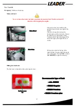
Page 18: ...he engine the higher the level will be Oil top up is done via the top of the right cylinder Top ups should be made on a cold engine Use the BMW wrench ref 2005749 to open the tank cap Filling the fuel tank The fuel level is checked on the control panel screen Never remove the motor oil tank cap when the motor is hot Wait for at least 25 minutes after stopping the engine Motor oil level Motor oil c...

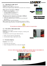
Page 19: ...n full power After having stopped the engine adjusted the max speed adjustment potentiometer Restart the engine to check the adjustment NB the engine s ECU Electronic control unit limits the speed to 7000rpm At this speed the engine can misfire It is therefore imperative not to exceed it CLEANING THE RADIATOR Frequency Every 50 hours When using in a very smoky environment the frequency of cleaning...

Page 20: ...er position Adjustment of the lowering speed Loosen to decrease the speed Pressure adjustment Loosen to decrease the pressure Max 150bars Filling cap In the event of malfunction of the pump if the table is in the up position to make it go back down operate the emergency valve Do not forget to put the valve back to its original position In the trunk On the chassis ON SKID version Trailer version ...

Page 21: ... Only use the K N cleaning product Air filter clogging indicator optional Principle The system permanently installed on Easy 4000 continuously monitors the level of filter clogging It allows you to decide whether or not to realise Service filters Use The indicator should be used at full engine speed Remove the filter Air fifter Collar Green area above 3 5KPa Filter in good condition Red zone below...

Page 22: ...he fan see5 12 To drain the gearbox oil Remove the lower cap Collect the used oil Refit the lower cap To fill the gearbox Check the tightening of the lower cap Remove the top cap Pour in 250ml 0 066Gal of oil Refit the upper cap Only use the following gearbox oil CASTROL SAF XJ75 140 YACCO BVX C100 85W140 Lower cap Waste container Oil level Top cap Valve cap 250ml 0 066Gal of oil ...

Page 23: ...used oil remove the oil filter Refit the purge cap taking care to replace the gasket Tightening torque 32Nm Fit a new oil filter tightening torque 11Nm Fill up to the correct level 4l when changing the filter NB The oil filter wrench ref 2005748 can be used to help you remove it Not supplied with the appliance Oil type 10w40 4 Stroke 100 synthetic Power1 Racing Never remove the motor oil tank cap ...

Page 24: ... interference suppressors from the 4 spark plugs Remove the spark plugs using a ref 2005751 wrench Fit 4 new spark plugs tightened to a torque of 20Nm for NGK DCPR8EKC Refit the 4 interference suppressors and the guards Spark plug cache under the cylinder Unscrew the 3 screws using a size 4 Allen wrench Spark plug cache at the end of the cylinder Must be removed from the bottom ...

Page 25: ...ture screws Refit the new fan making sure of its rotating direction Apply Loctite 2701 and new nylon ring counter nuts Refit the front grate Fuel filter Frequency Every 50 hours The fuel filter is located under the engine structure Remove the casing under the engine see 5 2 Remove the collars upstream and downstream of the fuel filter Take out and change the filter Make sure the fuel does not leak...

Page 26: ...ours The alternator belt is located to the rear of the engine Remove the rear engine casing Check the belt condition To change the belt Place the BMW tool ref BMW 12 3 591 on the belt Tool not supplied Turn the engine clockwise so that the tool slides between the pulley and the belt Remove the belt and install a new one Refit the rear casing checking for the presence of the blocks under the screws...

Page 27: ...Clean the radiator 2 The engine cuts off No more fuel Fill the fuel tank 1 The fuel filter is dirty Change the fuel filter 2 Insufficient air supply Clean or change the air filter 2 Dirty spark plugs Replace the spark plugs 2 The engine will not reach its maximum speed or operates erratically Dirty spark plugs Replace the spark plugs 2 Dirty air filter Clean or change the air filters 2 Rods out of...

Page 28: ...ant I60 20 074 Oil filter Filtre à huile 2005739 Oil filter tool Clé filtre à huile 2005748 Spark tool Clé a bougie 2005751 Oil filling tool Clé bouchon d huile 2005749 Spark plug Bougie 2005778 Maintenance kit Kit Maintenance gearbox oil motor oil oil filter gasket filling cap tool I60 30 100 Battery Batteries Odyssey PC625 2004210 10A Fuse Fusible 10A 2004629 ...

Page 29: ...2004506 Fan Hélice 2005734 Fuel pump Pompe à essence 2006127 ECU electronic control unit ECU electronic control unit 2006128 Lambda sensor Sonde Lambda 2006129 Spring exhaust gas Ressort pot d echappement 2005777 Hook for spring assembly Crochet de montage ressort 2005779 Oil cooler Radiateur 2004225 ...

Page 30: ...29 8 MAINTENANCE LOG BOOK Date Technician Hour meter Operation carried out ...

Page 31: ...30 9 ANNEXE Electrical wiring ...

Page 32: ...31 Remote control panel option ...

Page 33: ...32 Control panel electrical wiring ...

Page 34: ...33 Fan wiring ...

Page 35: ...nt of LEADER the claimant must return the equipment in the shortest possible time after discovery of the defect to the following address LEADER Maintenance Department ZI des Hautes Vallées Chemin No 34 CS 20014 76930 Octeville Sur Mer France OUT OF WARRANTY EQUIPMENT A complete analysis will be carried on your faulty equipment after which a detailed quote will be offered For faults and non warrant...

Page 36: ...35 Code Manual EASY4000 0 ZN3 45 EN 4 ...

Reviews: