background image

Summary of Contents for LAG-55

Page 1: ...MODEL LAG 55 AUDIO GENERATOR SINE SQUARE OPERATING INSTRUCTIONS Vr LEADER ELECTRONICS CORP...

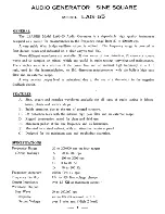
Page 2: ...evel is maintained due to the use of a thermistor in the negative feedback circuit FEATURES A Sine square and complex waveforms available for all types of audio testing in labora tories plants and ser...

Page 3: ...ignals for general audio measurements Due to the wide frequency range and a choice of waveforms it will find many uses in the laboratories service shops and manufacturing plants It is made up of the f...

Page 4: ...it elements under operating conditions The output of the three waveforms are selected and impressed on the cathode follower tube The generator outputs is taken from the cathode circuit and is adjustab...

Page 5: ...the amplifier or the apparatus under test should be as short as possible If a shielded cable is used it must have low capacitance especially when the measurements are to be made at the higher frequenc...

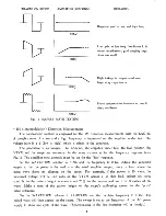
Page 6: ...in Fig 3 The LAG 55 is set for the SQUARE WAVE output and the frequency is varied from 20 to about 15 000 cps In an excellent amplifier the outp it waveform will be square without distortion over a wi...

Page 7: ...ner as for the frequency response tests Fig 3 The amplifier tone controls must be set for the flat response Set the WAVEFORM selector to SINE and the frequency to 2 Kc Adjust the generator output so t...

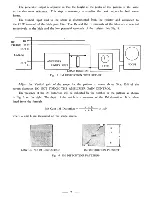
Page 8: ...gh and the low potential terminals of the resistor See Fig 5 Fig 5 IM DISTORTION TEST SET UP Adjust the Vertical gain of the scope for the pattern to cover about 50 to 75 of the screen diameter DO NOT...

Page 9: ...B The minus sign should not be omitted in the loss measurements TABLE I VOLTAGE RATIO DECIBELS VOLT RATIO for LOSS dB 1 VOLT RATIO for GAIN 0 333 9 54 3 0 0 286 10 9 3 5 0 250 12 0 4 0 0 222 13 0 4 5...

Page 10: ...V RESISTANCE in OHMS TABLE II POWER VOLTS DECIBELS POWER in WATTS VOLTS POWER in WATTS VOLTS SINE WAVE POWER RATIO DB SINE WAVE POWER RATIO DB 001 0 126 1COo 14 14 9 11 5 002 0 179 27 15 15 5 11 7 005...

Page 11: ...TABLE III VOLTAGE MULTIPLIER LOAD RESISTOR in OHMS MUL ITPLIER 3 2 0 447 4 0 500 8 0 707 12 0 865 20 1 12 32 1 42 50 1 77 100 2 50 250 3 95 600 6 13 KXK 7 90 2000 11 2 5000 17 7 10...

Page 12: ...LEADER ELECTRONICS CORP HEAD OFFICE NO 850 TSUNASHIMA CHO KOHOKU KU YOKOHAMA JAPAN BRANCH OFFICE NO 4 73 NIHONBASHI SUJI NANIWA KU OSAKA JAPAN 1966 8 500 Printed in Japan...

Reviews: