background image

Summary of Contents for LBO-51MA

Page 1: ...ICE MANUAL NOTE These servicing instructions are for use by qualified personnel only To avoid electrical shock do not perform any servicing other than that contained in the service manual unless you a...

Page 2: ......

Page 3: ...3 Sensitivity Adjustment 4 Frequency Response Check 3 7 X V PHASE adjustment 3 8 Z AXIS 4 TROUBLESHOOTING PROCEDURE 4 1 Troubleshooting Aid 1 4 2 Troubleshooting Aid 2 4 3 Troubleshooting Aid 3 1 Ove...

Page 4: ...BLOCK DIAGRAM 8 SCHEMATIC DIAGRAM 1 4 Power supply 2 4 CRT and Z AXIS amplifier 3 4 Xt Y pre amplifier 4 4 Xt Y final amplifier 9 PARTS LIST 10 CABINET REMOVAL 2 LBO 51MA Page 18 19 19 20 21 22 23 27...

Page 5: ...Power Requiremenla Storage Temperature Weight Operating Temperature DC to 3 MHz 3 dB 5 div ref 2 Hz to 3 MHz 3 dB 5 div ref Less than 120 nS Leu than 3 dog at 1 MHz 8 di v ref Within 6 AC or DC electe...

Page 6: ...m necessary for proper calibration of this instrument Test Equipment Multimeter Oscilloscope Sine Wave Generator Amplitude Calibrator Mi nimum Spec o 200V Accuracy 1 LEADER Model LDM 853A High voltage...

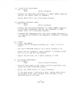
Page 7: ...t precaution to come into contact with the high voltage circuits 3 2 Initial Control Settings The initial control settings to be used for each check and adjustment are listed below Any variations from...

Page 8: ...focused display 3 5 1 Y AXIS Bias Adjustment Connect the DC voltmeter between pin 1 and 3 of P12 T 2510 Set the Y POSITION control for a meter reading of V Remove the DC voltmeter then reconnect it b...

Page 9: ...and observe the generator frequency is greater than 3MHz 3 6 1 X AXIS Bias Adjustment Connect the DC voltmeter between pin 1 and 3 of Pl1 T 2510 Set the X POSITION control for a meter reading of V Rem...

Page 10: ...quency is greater than 3MHz 3 7 X Y Phase Adjustment Set X AXIS GAIN Y AXIS GAIN Fully clockwise Fully clockwise Connect the sine wave generator to X and Y INPUT connectors with matching length cables...

Page 11: ...ol for a DC level as shown in Figure 3 1 Increase the frequency until the sine wave amplitude decreases to 2 8 division 14Vp p and observe the generator frequency is greater than 4MHz 60V d 40V OV Fig...

Page 12: ...to come into contact with the high voltage circuits 4 2 Troubleshooting Aid 2 The oscilloscope consists of three major sections which are the high voltage power supply Y AXIS amplifier and X AXIS amp...

Page 13: ...2 T 2510 if necessary b Connect pin 1 and 3 of P12 T 2510 with short clip lead for balancing check of Y AXIS amplifier Spot appears Yes Connect pin 1 and 3 of P10 T 2510 with short clip lead Spot appe...

Page 14: ...w sensitivity Connect the amplitude calibrator to X AXIS INPUT connector and set the output voltage to 200mVp p Set the controls as paragraph 3 2 Initial Control Settings Trace the waveform from the i...

Page 15: ...RIGHT SIDE VIEW X AXIS BIAS OV P11 VR12 V1 T 2510 r t I Y C 3 0 3 15V rj z 1 3 t 0 0 r 3 H 0 z C...

Page 16: ...r IJ J 01 1 CJ1 I s LEFT SIDE VIEW Y AXIS T 2511 X AXIS T 251J...

Page 17: ...Q 8 0_ 90 I 0 0 oo o RS C2 B2 RII _ R4 __ AIO J L 03 6 2 E O D I R D O D I R e CV E 8 ICI 0 E YP2 __ J n I W I I VWIg 081 gI 3 o D R20 R21 H H R22 0 O _f RI9 CII OR9 E O a 0 E RI6 CIO n N 00 R2J CI8...

Page 18: ......

Page 19: ...RI9 R23 RS3 RSS 8 e OiG RSG B Oi7 07 JIIIi IL E B RIS RI4 RG VRI DC BAL ID U p x y PiU AMP RIO RII OG B E RS RI2 as E B 04 R3 B 0 E 02 E 01 E r 2511 R9 C2 Go5 R29 03 S G R2 R4 R87 I RIOIO I M et 11 1...

Page 20: ......

Page 21: ...T 2512 ooQo VR4 ROTAT ION VR3 FOCUS VR I INTEN 131 11 11 11 11 11 11 P25 CRT CONTROL u T 2512 p T 2513 00000 VR2 Y pos Y GAIN YR4 X POS X GAIN I 11 12 11 P26 X Y CONTROL T 2513 p 17 LBO 51MfI P27...

Page 22: ...IY INPUT Y AXIS I I I Y AXIS FINAL AMP Q41 47 1900V CRT INPUT I X AXIS FINAL AMP t5kV J tJj t i 0 0 I 1 CX t J I T 2510 H Iz INPUT I Z AXIS 0 0 s Q7 t15V 15V t150V FEED BACK t22V Unreg AMP Q8 10...

Page 23: ...815 C6 C1 50V 35V III 2200j LF MAIN RC B TPI 150V C3 250V 4 1 1 15 V CS 25 V lOll TP3 I 5 V ea 25V 10 T 2510A _ 13 26 30 11 20 33 40 u5 EQ J O E D _ R 1 n J 119 j 31 34 68 70 90 100 Cl v 59 25 v30 48...

Page 24: ......

Page 25: ...I INTEN I 1 2 31 150V 4 ASTIG 5 5 1 61 FOCUS 6 1 7 I s FOCUS I I 1 1 9 19 I I GND IIO 1 1 10 A T 12 ROTATION I 1r 0 i __ USEJL 131 15V 13 I T 2460 L J I RI VI J22 24 P22 24 1T 2512 2 __ _ RI 1 I _ VR...

Page 26: ......

Page 27: ...J J NOT USED V3 39 73 80 CI5 20 11 28 QI2 20 RoO RS8 IIIK Q5 25e1815 GR R45 4 7K C25 25V 10P X Y PRE AMP p e s _____________ I T 2511 INV R 5 2 270 R56 2 70 R61 5 6K Ro5 100 R63 lOO Q30 25C 1359 Ro6...

Page 28: ......

Page 29: ...RI12 lOO R83 lOO R80 lOO R 11 0 100 RI06 220 VC2 40P R76 390 R81 100 0 42 25CI953 Q48 25C1953 0 41 25CI953 R73 1 I K R15 3 3K R74 I K R71 100 VR 11 3 3K Y BIAS Rn 2 7K J 10 PlO C51 1 jl 0 01111 A 2 1...

Page 30: ......

Page 31: ...104004 METAL O 1DE OaK OHt1 5 IIJ R68 1010222004 CARBON FILM 2 2K OHM 5 1 441 1010829002 CARBON FILM 8 2 OHM 5 1 41J R71 1010101002 CARBON FILM 10 OHM 5 1 41J 1010223006 CARBOH FILM 22K OHM 5 1 41 1 R...

Page 32: ...23D568L Cl 2330044003 ELECTROLYTIC 100uF 20 315 1 Q8 3011015003 P P 2SA1015 0 or Y C2 2120470016 MICA 47pF 1O 500Y Q9 3031815009 HPH 23C1815 0 or Y C3 2280479014 ELECTROLYTIC 4 7uF 20 1 250 1 Q10 3011...

Page 33: ...0 10 I T 2511 OI lT J v PJRBLE E 0R R 1 0 l JR I t IR I 0 I P I J I CAPAC I TOR Cl 21601040j 9 C2 218010 3002 C3 2240100015 C4 2010103005 C5 2240100015 C6 2010103005 C7 2010103005 C8 2240100015 C 2010...

Page 34: ...R 1S1588 R40 1331004008 METAL FILM 1 0OM OHM 1 1 2W 031 3110006004 DETECTOR IS1588 R41 t 01 0221 002 CARBON FILM 220 OHM 5 1 4 032 3110006004 DETECTOR IS1588 R42 1010474001 CARBOi FILM 470K OHM 5 1 41...

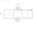
Page 35: ...10 CABINET REMOVAL _ Take eight screws off to remove the Top cover _ Take two four screws to remove the Bottom cover 27 LBO 51 MA...

Page 36: ......

Reviews: