background image


TABLE OF CONTENTS 

GENERAL SAFETY SUMMARY ......................................................................................... I


1.


INTRODUCTION ........................................................................................................ 1


1.1


Scope of Warranty .................................................................................................................. 1


1.2


Operating Precautions ............................................................................................................ 2


1.2.1


Maximum Allowable Input Voltage ................................................................................... 2


1.2.2


Mechanical Shock............................................................................................................ 2


1.2.3


Electrostatic Damage....................................................................................................... 2


1.2.4


Warming Up..................................................................................................................... 2


1.3


Trademark Acknowledgments................................................................................................. 2


2.


SPECIFICATIONS ...................................................................................................... 3


2.1


General ................................................................................................................................... 3


2.2


Features.................................................................................................................................. 3


2.3


Specifications.......................................................................................................................... 3


2.3.1


Waveform Input ............................................................................................................... 3


2.3.2


Waveform Output............................................................................................................. 4


2.3.3


Control Connectors.......................................................................................................... 4


2.3.4


Automatic Self Check ...................................................................................................... 4


2.3.5


Measurable Items ............................................................................................................ 5


2.3.6


General Specifications ..................................................................................................... 6


3.


PANEL DESCRIPTION............................................................................................... 7


4.


BEFORE YOU BEGIN MEASURING ......................................................................... 8


4.1


System Overview .................................................................................................................... 8


4.2


Installing the USB Driver......................................................................................................... 9


4.3


Starting the PC Application ................................................................................................... 13


5.


HOW TO USE........................................................................................................... 14


5.1


Measurement Procedure ...................................................................................................... 14


5.2


PC Application Description.................................................................................................... 16


5.2.1


Measurement Window ................................................................................................... 16


5.2.2


Window Setting.............................................................................................................. 18


6.


REMOTE CONTROL................................................................................................ 20


6.1


Command Structure.............................................................................................................. 20


6.2


Commands ........................................................................................................................... 21


6.3


Command Details ................................................................................................................22


Summary of Contents for LE 8682

Page 1: ...LE 8682 VIDEO MEASURING BOX INSTRUCTION MANUAL...

Page 2: ...ns 3 2 3 1 Waveform Input 3 2 3 2 Waveform Output 4 2 3 3 Control Connectors 4 2 3 4 Automatic Self Check 4 2 3 5 Measurable Items 5 2 3 6 General Specifications 6 3 PANEL DESCRIPTION 7 4 BEFORE YOU B...

Page 3: ...tand If you have any questions about the contents of this manual please contact your local LEADER agent Symbols and Terms The following symbols and terms are used in this instruction manual and on the...

Page 4: ...e instrument has condensation within it wait for approximately 30 minutes before turning on the power Operating Humidity Range Use this instrument in an environment whose relative humidity is 85 RH or...

Page 5: ...e power outlet do not pull on the cord Pull from the plug Warnings Concerning Grounding The instrument has a ground terminal to protect the user and the instrument from electric shock Ensure that the...

Page 6: ...h with mild detergent and wipe gently While cleaning make sure that foreign materials such as water and detergent do not enter the product If liquid or a metal object enters into the instrument fire o...

Page 7: ...r to it when necessary 1 1 Scope of Warranty This LEADER instrument has been manufactured under the strictest quality control guidelines LEADER shall not be obligated to furnish the following free ser...

Page 8: ...s dropped or otherwise exposed to a strong shock 1 2 3 Electrostatic Damage Electronic components can be damaged by static discharge Static electricity can build up in the core wire of a coaxial cable...

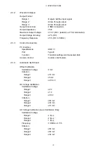
Page 9: ...its own measurement levels in the waveform measurement section 2 3 Specifications 2 3 1 Waveform Input Input Signal NTSC or PAL composite video signal Input Connector 1 BNC connector Input Impedance 7...

Page 10: ...ace Specifications USB 1 1 Port Type B Function Transmits settings and measured data Camera Control Custom order feature 2 3 4 Automatic Self Check Offset Calibration Calibration Voltage 0 mV Criterio...

Page 11: ...asurement Accuracy in section 2 3 1 Waveform Input Burst Frequency Description Measures the frequency of the color burst signal Measurement Range 3 to 4 MHz Measurement Accuracy 0 1 25 5 C Burst Level...

Page 12: ...nal Measurement Range Range 1 3 V Range 2 1 5 V Range 3 0 75 V Measurement Accuracy See Voltage Measurement Accuracy in section 2 3 1 Waveform Input 2 3 6 General Specifications Environmental Conditio...

Page 13: ...ough 3 CONTROL custom order feature Controls a camera and supplies power For details contact your nearest LEADER agent 4 USB Connects to a PC and receives LE 8682 settings and measured values from the...

Page 14: ...T You can retrieve the measured values from a PC that is connected to the LE 8682 through USB OUTPUT 1 and 2 provide active through output of the signal received through INPUT Connect image processing...

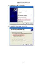
Page 15: ...LE9280_04B_CommClass_32 inf USB driver 32 bit version LE9280_04B_CommClass_64 inf USB driver 64 bit version Instruction_Manual_for_LE_8682 PC_SOFT 1 Load the supplied CD ROM in your PC 2 Connect the A...

Page 16: ...4 BEFORE YOU BEGIN MEASURING 10 5 Select Install from a list and click Next 6 Select Search removable media and click Next...

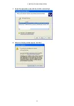
Page 17: ...4 BEFORE YOU BEGIN MEASURING 11 7 Select the appropriate version 32 bit or 64 bit and click Next 8 When the following window appears click Next...

Page 18: ...4 BEFORE YOU BEGIN MEASURING 12 9 When the following window appears the installation is complete Click Finish You can check the installed USB driver under Ports in Device Manager...

Page 19: ...location of your choice To start the PC application click LE8682Soft exe CD ROM DRIVER Instruction_Manual_for_LE_8682 PC_SOFT Release_ Copy to the PC LE8682Soft exe PC application LE8682Soft exe confi...

Page 20: ...OPEN appears at the lower left of the window If you cannot select the COM port close the PC application and remove the USB cable Reconnect the cable and restart the PC application 5 On the Setting men...

Page 21: ...y The available window numbers are those whose EN check boxes have been selected in the Window Setting window 7 Apply an NTSC PAL composite video signal to the INPUT connector of the LE 8682 8 Click M...

Page 22: ...lication starts 1 Menu Menu Description Window Setting Set the measurement range Reference 5 2 2 Window Setting Setting Level unit Set the level display unit to mV or IRE Help Version Inf Displays the...

Page 23: ...measurements Therefore no value will appear until 10 measurements have been made 5 Signal Level A to H Displays the input signal levels for the measurement range corresponding to the selected Window...

Page 24: ...window is used to set measurement ranges Window Setting is not available when the PC and LE 8682 are not connected You can set up to 32 measurement ranges On the measurement window eight ranges that y...

Page 25: ...ly Enter a larger number for End Line than Start Line Also set the difference between the start and end lines to 20 or less Start Time End Time us Enter the measurement start and end times in the rang...

Page 26: ...Delimiter LF 0x0A Response When the LE 8682 appropriately receives a Tx command it returns A ACK Depending on the command the LE 8682 returns a setting when a question mark is specified for a paramet...

Page 27: ...ueries the burst frequency 6 BSTLEV p1 Queries the burst level Sets the measurement range p1 1 to 32 Selects a window p2 300 to 3411 Sets or queries the start time p3 21 to 263 283 to 525 Sets the sta...

Page 28: ...GE 1 Sets range 1 Response A ACK Tx RANGE Queries the range Response RANGE 1 Range 1 2 Queries the V sync frequency Tx Command VFRQ Response Message 1 digit integer 3 digit decimal 2 digit exponent Hz...

Page 29: ...lts 5 Queries the burst frequency Tx Command BSTFRQ Response Message 1 digit integer 6 digit decimal 2 digit exponent Hz Example Tx BSTFRQ Queries the burst frequency Response BSTFRQ 3 579919E 06 3 57...

Page 30: ...sponse A ACK Tx VIDEOWIN 1 Queries the measurement range of window 1 Response VIDEOWIN 1 300 21 500 30 Returns the measurement range of window 1 8 Queries the video signal level Tx Command Command Tx...

Page 31: ...ications 3 Both DC calibration and AC calibration are outside the specifications Example Tx CHECK Executes self check Response CHECK NG 123 Self check failure Range 1 DC calibration is outside the ran...

Page 32: ...LE 8682 2006 2 28 SJ T11364 2006 Hazardous Substances in each Part Parts Pb Hg Cd Cr PBB PBDE SJ T11363 2006 SJ T11363 2006 Ver 1 Following information is for Chinese RoHS only...

Page 33: ...LEADER ELECTRONICS CORP 2 6 33 Tsunashima Higashi Kohoku ku Yokohama 223 8505 Japan PHONE 81 45 541 2123 FAX 81 45 541 2823 http www leader co jp Nov 11 2013 Ver 1 SW Ver 1 00...

Reviews: