EXTERNAL CONTROL INTERFACE
■
8-7
8-7 REMOTE DIRECT RECALL
This function remotely controls the memory direct recall.
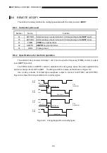
8-7-1 Connector pins used
Number
Name
Function
1
STB
Connects a timing pulse for reading data.
2 to 9
P1
0
to P1
7
Connects address data. (port 1)
10
BUSY
Outputs a signal informing the generator cannot receive data.
19
GND
Frame ground
8-7-2 Specifications for electrical operation
For the pins P1
0
to P1
7
, set the address data of 00 to 99 in BCD code. Given below are the
relationship between a signal to be applied to each connector pin and its address data.
Input signal
P1
7
P1
6
P1
5
P1
4
P1
3
P1
2
P1
1
P1
0
Address data
0
0
0
0
0
0
0
0
0
0
0
0
0
0
0
0
1
1
…
…
…
…
…
…
…
…
…
0
0
0
0
1
0
0
1
9
0
0
0
1
0
0
0
0
10
…
…
…
…
…
…
…
…
…
1
0
0
1
1
0
0
1
99
0: Low (
=
0 V) 1: High (
=
5 V)
After the address data is set, applying a timing pulse to the STB pin causes the memory at the set
address to be recalled. Figure 8-4 shows the timing condition for each connector.
Min 10 µs
Min 1 µs
Max 50 ms
P1
0
to P1
7
STB
BUSY
Figure 8-4 Timing diagram for address data


