background image

OPERATION


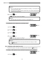
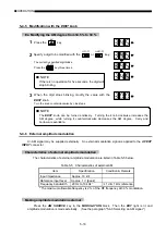
5-6-2


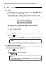
Turning main- / sub-channel signals ON or OFF 

1

 Press 

the 

FM-SIG

 key. 

Pressing this key switches FM between ON and OFF.    The key light is lit in the ON case, and it is lit off in 
the OFF case.


 NOTE

Even after main- / sub-channel signals are turned OFF, the 

MODULATION

 readout still

shows an FM ratio.


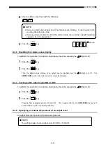
2

  Press either one of the 

MODULATION

 block keys (

L=R

L

R

, and 

L=

R

) to 

select a desired modulation mode. 

The key light corresponding to the selected modulation mode is lit.


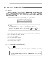
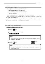
5-6-3


Selecting a modulation signal 


A modulation signal can be selected among the following three: 

 The internal sine wave of 400 Hz or 1 kHz (INT) 

 An externally supplied signal of 20 Hz to 15 kHz (EXT) 

 DDS sine wave (DDS) 


Select a desired signal using the 

FM SOURCE

 key in the 

MODULATION

 block. 


Every press toggles a signal among INT, EXT, and DDS. The selected signal can be identified from 

the 

INT

EXT

, and 

DDS

 lights. 


Once INT is selected, press the 

INT

 key to switch a frequency between 400 Hz and 1 kHz.    The key 

light is lit when 1 kHz is selected.    It is lit off when 400 Hz is selected. 


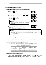
5-6-4


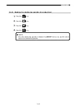
Direct setting with the data keys 


Ex. Setting an FM ratio to 85 %


1

 Press 

the 

FM

 key. 

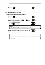
2

  Enter an FM ratio with the data keys. 

8

5


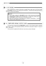
 NOTE

If a wrong value is entered, confirm the entered value once, and then repeat the setting
operation from the procedure 1.


5-23 

Summary of Contents for LG 3219

Page 1: ...LG 3219 LG 3238 RDS SIGNAL GENERATOR AM FM STEREO SIGNAL GENERATOR INSTRUCTION MANUAL ...

Page 2: ...a potentially hazardous situations which if not heeded should result in death or serious injury CAUTION Indicates a potentially hazardous situations which if not heeded could result in minor or moderate injury or machine damage Precautions that must be kept are divided with marks shown below and their meanings are described Some of the marks are given below This mark describes matters which users ...

Page 3: ...pair of the damaged power cable or power plug contact the dealer or representative from which you purchased the product 電源コードの保護接地端子は必ず接地する Do not attempt to damage the power cable and power plug Clean dust off the power plug periodically Improper insertion may cause an electric shock or fire due to the heated plug Never use a damaged plug or loose socket outlet Surely insert the power plug to the...

Page 4: ...mixed with general household waste For proper treatment recovery and recycling please take these products to designated collection points where they will be accepted on a free of charge basis Alternatively in some countries you may be able to return your products to your local retailer upon the purchase of an equivalent new product Disposing of this product correctly will help to save valuable res...

Page 5: ...7 RS 232 C interface 1 8 1 4 8 External control interface 1 8 CHAPTER 2 SPECIFICATIONS 2 1 ELECTRICAL PERFORMANCE 2 1 2 2 ENVIRONMENTAL CONDITIONS 2 7 2 3 MECHANICAL PERFORMANCE 2 8 2 4 ACCESSORIES 2 8 2 5 WIRING REQUIREMENTS 2 8 2 6 REGULATORY INFORMATION 2 9 CHAPTER 3 INSTALLATION 3 1 POWER REQUIREMENT 3 1 3 2 FUSE 3 1 3 3 POWER CABLE 3 2 3 4 CONNECTING TO OTHER EQUIPMENT 3 2 3 5 INSTALLING ON A...

Page 6: ...ion with the EDIIT knob 5 9 5 3 4 Relative value display 5 9 5 3 5 Specifying a relative output level value 5 10 5 3 6 Disabling the relative value display 5 11 5 3 7 Turning an RF output signal ON or OFF 5 11 5 3 8 Specifying a variable step amount of an output level 5 11 5 3 9 Changing an output level with a variable step amount 5 12 5 3 10 Disabling the variable step operation of an output leve...

Page 7: ... data with the EDIIT knob 5 32 5 11 7 Selecting a sub carrier phase 5 32 5 12 TRI ARI SIGNAL LG 3219 only 5 33 5 12 1 General 5 33 5 12 2 Turning an SK signal ON or OFF 5 34 5 12 3 Direct setting of an SK signal level with the data keys 5 34 5 12 4 Modification of an SK signal level with the EDIIT knob 5 34 5 12 5 Turning a BK signal ON or OFF 5 35 5 12 6 Direct setting of the AM degree of a BK si...

Page 8: ...6 4 6 7 1 Local mode 6 4 6 7 2 Remote mode 6 5 6 7 3 Remote mode with lockout 6 5 6 8 RESPONSE TO COMMANDS 6 5 6 9 PROGRAM CODE INPUT FORMAT 6 6 6 9 1 Input program message format 6 6 6 9 2 Delimiter for a program message 6 6 6 9 3 The end code 6 6 6 9 4 Program code input format 6 7 CHAPTER 7 RS 232 C INTERFACE 7 1 GENERAL 7 1 7 2 INTERFACE SPECIFICATIONS 7 1 7 3 RS 232 C CONNECTOR 7 1 CHAPTER 8 ...

Page 9: ...peration 8 6 8 7 REMOTE DIRECT RECALL 8 7 8 7 1 Connector pins used 8 7 8 7 2 Specifications for electrical operation 8 7 8 8 CONTROL OUTPUT 8 8 8 8 1 Connector pins used 8 8 8 8 2 Readout 8 8 8 8 3 Operating procedure 8 8 8 9 RELAY DRIVE OUTPUT 8 10 8 9 1 Output connector 8 10 8 9 2 Operating procedure 8 11 APPENDIX GP IB Program code list ...

Page 10: ...ting the instrument CHAPTER 4 NAMES AND FUNCTIONS OF THE OPERATIONAL PARTS Describes names and functions of each operation part of the instrument CHAPTER 5 OPERATION Explains each function on the panel and the operation procedures of the signal generator CHAPTER 6 GP IB INTERFACE This chapter describes in detail how to use the GP IB interface to operate this product CHAPTER 7 RS 232 C INTERFACE De...

Page 11: ...an be used to directly read out increment or decrement from a predetermined reference output level Also setting a variable step amount allows an output level to be changed at a desired step amount This series of instruments provide modulation of FM and AM and also mixed AM FM modulation by combining internal and external modulation signals This series generates composite stereo modulation signals ...

Page 12: ...put signal parameters The instrument modifies any digit of the parameters for an RF frequency output level and modulation status with the rotary knob 7 Remote control The instrument is equipped with the GP IB RS 232 C and external control interfaces at standard 8 Weather band output The instrument provides RF outputs ranging from 162 000 0 to 163 000 0 MHz available for FM monophonic modulation on...

Page 13: ...e figure is considered by EBU as a traffic information signal This frequency range is called the second sub channel in Japan The instrument contains the functions of both a stereo modulator and signal generator as shown in Figure 1 2 100 45 10 Level ratio unit 50 15 k 23 k 38 k 53 k 99 k Frequency unit Hz 19 k Monophonic signal Main channel or L R channel Pilot signal Sub channel or L R channel SC...

Page 14: ...l As a test tone an internal AF signal or an externally supplied sine wave ranging from 20 Hz to 15 kHz can be used e R mode A test tone is applied only to the R input in Figure 1 2 to generate a composite stereo signal The resultant signal composes of the main and sub channel signal components with the same level When demodulated in a stereo receiver the signal appears only at the R channel As a ...

Page 15: ...ries and RBDS signals that are defined in NRSC NAB and broadcasted in the United States Except for a little difference in usage because of different broadcasting areas the RDS signals and RBDS signals are same in modulation method transmission method and data structure Thus in the rest of this manual it is assumed that the RDS signals include the RBDS signals unless otherwise specified Listed belo...

Page 16: ...TRI signals Item Specification Sub carrier SK 1 Frequency 57 kHz FM deviation 4 kHz only TRI 3 5 kHz both RDS TRI Modulation method AM Announcement signal DK 2 Modulation frequency 125 Hz 57 kHz 456 AM degree 30 Area signal BK 3 Modulation frequency A 23 75 Hz 57 kHz 2 400 B 28 27 Hz 57 kHz 2 016 C 34 93 Hz 57 kHz 1 632 D 39 58 Hz 57 kHz 1 440 E 45 67 Hz 57 kHz 1 248 F 53 98 Hz 57 kHz 1 056 AM deg...

Page 17: ...e local RL1 Complete capability Parallel poll PP0 No capability Device clear DC1 Complete capability Device trigger DT0 No capability Controller C0 No capability 1 4 7 RS 232 C interface Shown below is the RS 232 C interface of these instruments Table 1 4 RS 232 C interface Item Specification Baud rate 38 400 bps Character length 8 bits Parity EVEN Flow control Xon Xoff Stop bit 1 bit 1 4 8 Extern...

Page 18: ...evel 0 dBµV emf 2 0 dB Output level 0 dBµV emf Output impedance 50 Ω VSWR 1 3 Output level 101 dBµV Attenuator contact Semiconductor Spectral purity Item Specification Condition Remark Spurious output signals Harmonics 2nd 3rd 30 dBc Non harmonics 50 dBc Band 2 to 3 40 dBc Band 1 0 1 MHz fs 35 MHz 30 dBc Band 1 fs 35 000 1 MHz At a point of 10 kHz or more from the carrier fs Spurious output freque...

Page 19: ...e 0 to 80 Modulation degree indication range 0 to 100 Resolution 0 5 0 to 100 Accuracy Set value 0 1 1 Band 1 0 4 MHz to 1 7 MHz Set value 0 1 2 Band 1 to 3 0 15 MHz to 140 MHz Represented as a modulation degree at the 1 kHz modulation frequency The maximum set value is 80 Distortion factor Band 1 0 4 MHz to 1 7 MHz 0 5 0 to 30 AM 1 5 30 to 60 AM 3 60 to 80 AM Band 1 to 3 0 15 MHz to 140 MHz 1 5 0...

Page 20: ... µs Separation for MPX stereo signals 55 dB Frequency 76 MHz to 108 MHz Modulation frequency 1 kHz 100 modulation 67 5 kHz deviation Incidental AM 0 5 10 7 MHz 1 MHz 76 MHz to 108 MHz At 75 kHz deviation with the modulation frequency of 1 kHz External modulation frequency response MONO mode 1 dB 20 Hz to 100 kHz reference to 1 kHz Other modes than MONO mode 1 dB 20 Hz to 15 kHz reference to 1 kHz ...

Page 21: ...quency of 1 kHz Post detection bandwidth 50 Hz to 15 kHz De emphasis 50 µs Pre emphasis 25 µs 50 µs 75 µs OFF Increase characteristic at the OFF standard FM AM mixed modulation Item Specification Condition Remark FM mono AM mixed modulation 1 FM mono EXT AM INT 2 FM mono INT AM EXT 3 FM mono EXT AM EXT 4 FM mono INT AM INT FM stereo AM mixed modulation 1 FM stereo EXT AM INT 2 FM stereo INT AM EXT...

Page 22: ...signal Frequency accuracy 125 Hz 57 kHz 456 1 AM degree range 0 to 40 AM resolution 1 AM accuracy 5 AM distortion factor 1 SK 5 3 AM 30 BK signal Frequency accuracy Code A 23 75 Hz 57 kHz 2 400 1 Code B 28 27 Hz 57 kHz 2 016 1 Code C 34 93 Hz 57 kHz 1 632 1 Code D 39 58 Hz 57 kHz 1 440 1 Code E 45 67 Hz 57 kHz 1 248 1 Code F 53 98 Hz 57 kHz 1 056 1 AM degree range 0 to 80 AM resolution 1 AM accura...

Page 23: ... dB With reference to 57 kHz Input impedance Approx 10 kΩ COMP OUTPUT Output terminal for monitoring modulation signals Output voltage Approx 5 V P P Terminated at 600 Ω FM mono 100 kHz Output impedance Approx 600 Ω PILOT OUTPUT Output in modulation modes other than the MONO mode Output voltage Approx 1 V rms Output impedance Approx 1 kΩ GP IB Function Code Description Source handshake SH1 Complet...

Page 24: ...Relay drive output Output voltage Approx 5 V Output current Approx 50 mA Power requirement Item Specification Condition Remark Mains voltage 90 V to 250 V Mains frequency 50 Hz 60 Hz Power consumption 60 VA 2 2 ENVIRONMENTAL CONDITIONS Temperature and relative humidity range Item Specification Condition Remark Limit range of guaranteed performance 10 to 35 20 to 85 RH Limit range of operation 0 to...

Page 25: ... CD 1 For LG 3219 only 2 5 WIRING REQUIREMENTS Wiring requirements Location Item Cable name Product specifications Requirements AF EXT INPUT cable 3 m BNC type shielded Front panel RF OUTPUT cable 3 m BNC type shielded AC Power cable 3 m attached RS 232 C interface cable 3 m shielded GP IB interface cable 5 m metal shell shielded EXT CONTROL I O interface cable 3 m shielded DRIVE OUTPUT cable 3 m ...

Page 26: ...and has been supplied in a safe condition This instruction manual contains information and warnings which must be followed by the user to ensure safe operation and to maintain the instrument in a safe condition NOTICE This signal generator is complied with emission limits for the Class A equipment However be carefull that this signal generator may cause radio frequency interference only at frequen...

Page 27: ...ecified supply voltage Before connecting AC power to the instrument be sure that the supply voltage is within the range from 90 V to 250 V WARNING 3 2 FUSE Verify the proper fuse is installed in the fuse holder Ratings of the fuse are noted on the rear panel and listed below Use the specified fuse Make sure that only fuses with the required rated current and of the specified type are used for repl...

Page 28: ...nt The interconnections are made with input output coaxial connectors on the front panel and RCA type pin connector GP IB connector RS 232 C connector EXT CONTROL I O connector and coaxial connectors on the rear panel All outer metal shells of coaxial connectors and RCA type pin connector are directly connected to the chassis and frame of the instrument No hazardous voltage will appear on any pin ...

Page 29: ...nment After the life is over replacement will be needed to avoid insufficient back up The battery should be treated as indicated in the battery s instruction for use Removal of the instrument s cover is only permitted to a qualified personnel Contact the dealer or representative from which you purchased the instrument in such a case 3 8 INSTALL OF EDITOR LG 3219 only The instrument provides softwa...

Page 30: ...e reverse connection cable 3 8 3 Install of editor Turn on the computer and run Microsoft Windows Insert the supplied floppy disk Editor Setup Disk into the floppy disk drive Select the START DESIGNATE A FILE NAME AND EXECUTE Enter drive name setup in the COMMAND LINE box and select the OK button If the floppy disk is set in the drive A enter A setup and select the OK button The installation scree...

Page 31: ...this series of signal generators This paragraph gives you the name of each section and brief description of its function able in the relevant partially magnified figure Note that the overall view of the model LG 3219 is used to shown the position of each block on the panel Also the detailed description of each block is avail 1 2 1 POWER switch Turns the mains power ON or OFF Press the switch to tu...

Page 32: ...re emphasis µs 3 1 3 1 Unit light The Unit light corresponding to the displayed value is lit 4 TRI RDS readout for LG 3219 only Indicates various values related to TRI ARI signals and RDS signals The following table lists the details of values Description Unit light 4 1 RDS level RDS pattern number PAT CODE RDS sub carrier phase deg TRI SK level TRI BK DK signal modulation degree TRI code number P...

Page 33: ...relative RF level is set 6 1 6 2 7 OUTPUT connector A BNC receptacle for supplying RF output signals 8 EDIIT block Used for the setting operation as described below Common RF frequency Output level AM degree FM deviation FM stereo modulation ratio Pilot level and DDS frequency option LG 3219 only RDS level SK level of TRI RDS pattern selection BK modulation degree and DK modulation degree 8 1 keys...

Page 34: ...a reverse frequency of a relay drive output 10 3 INTVL key Press this key following the SHIFT key 16 to enable the interval time setting mode in the auto sequence operation of the assorted preset memory 10 4 I O MODE key Press this key following the SHIFT key 16 to specify the I O mode of GP IB external control interface or auto sequence of the assorted preset memory 10 5 PORT 1 key Press this key...

Page 35: ... lit 11 1 11 2 11 3 11 4 11 5 11 6 11 7 11 8 11 1 RF FREQ key Press this key to enable the setting operation for an RF frequency 11 2 AMPTD key Press this key to enable the setting operation for an output level 11 3 FM key Press this key to enable setting operation for frequency modulation 11 4 AM key Press this key to enable the setting operation for amplitude modulation 11 5 DDS key option Press...

Page 36: ... enable the setting mode for an TRI code number In either case the PAT CODE light in the TRI RDS readout 4 is lit 12 3 SK key Press this key to turn TRI SK signal output ON or OFF In the ON case the relevant light is lit 12 4 BK AM B key Press this key to turn TRI BK signal output ON or OFF In the ON case the relevant light is lit Press this key following the SHIFT key 16 to enable the setting mod...

Page 37: ... turn amplitude modulation AM ON or OFF In the ON case the relevant light is lit 13 7 FM SIG key Press this key to turn frequency modulation FM ON or OFF In the ON case the relevant light is lit 13 8 PILOT key Press this key to turn pilot signal output ON or OFF In the ON case the relevant light is lit Note that pilot signal output cannot be turned OFF when the modulation mode is set to MONO 13 9 ...

Page 38: ...nal modulation signal The light is lit when 1kHz is selected and lit off when 400 Hz is selected 14 3 AM SOURCE FM SOURCE key Used to select a modulation signal source for each AM and FM Press keys to select either INT internal signal source or EXT external signal source If the optional DDS signal source is provided you may select DDS too In either case the relevant light is lit 15 REMOTE LOCAL ke...

Page 39: ... RCL key Press this key to specify a group in the direct or sequential recall operation of the assorted preset memory 17 5 AUTO MANU key Press this key following the SHIFT key 16 to start or stop the auto sequence operation of the assorted preset memory 17 6 COPY key Press this key following the SHIFT key 16 to transfer the contents of the assorted preset memory to another signal generator via GP ...

Page 40: ... 22 MAINS INPUT 23 input fuse 24 EXT CONTROL I O the external control interface 25 DRIVE OUTPUT obtaining a signal for an external relay drive 26 SCA tacle for obtaining the SCA signal externally 27 obtaining an FM stereo modulation signal 28 cle for obtaining the PILOT output signal A 9 pin connector for co connector A 25 pin connector switch Selects a mains voltage appropr connector Accepts a po...

Page 41: ... associated with each operation 5 2 RF FREQUENCY 5 3 OUTPUT LEVEL 5 4 AMPLITUDE MODULATION AM 5 5 FREQUENCY MODULATION FM 5 6 MAIN AND SUB CHANNEL SIGNALS OF FM STEREO LG 3238 LG 3219 only 5 7 PILOT SIGNAL 5 8 PRE EMPHASIS 5 9 SCA SIGNAL 5 10 COMPOSITE SIGNAL OUTPUT LEVEL 5 11 RDS SIGNAL LG 3219 only 5 12 TRI ARI SIGNAL LG 3219 only 5 13 DDS FREQUENCY 5 14 ASSORTED PRESET MEMORY 5 1 ...

Page 42: ...MODIFY knob cannot used for this switching See the paragraph 5 2 2 Direct setting with the data keys In the case of the relative value display an actual frequency always falls within the allowable setting range The relative value display is enabled when the F light is lit in the FREQUENCY readout See the paragraph 5 2 4 Relative value display The basic operations related to RF frequency are explai...

Page 43: ...e value from 123 456 7 MHz to 123 457 0 MHz 1 Press the RF FREQ key 2 Specify a digit to be modified with the ΔF OFF or ΔdB OFF key The currently specified digit blinks Press the ΔF OFF key three times NOTE If there is no operation for five seconds the digit will stop blinking 3 When the digit stops blinking modify the value with the EDIIT k Turn the knob clockwise by three steps nob NOTE The MODI...

Page 44: ...F FREQ key 4 Enter a reference frequency with the data keys 1 0 0 NOTE Be sure to start numeral input while The data keys are blinking Once they are lit off you may not enter any value If a wrong value is entered confirm the entered value once and then repeat the setting operation from the procedure 1 5 Press the ENTER key The F light is lit and a relative value is displayed NOTE The setting range...

Page 45: ... reference frequency 1 Press the SHIFT key 2 Press the REF 7 key 3 Press the RF FREQ key NOTE The reference frequency cannot be verified as long as the relative value display is disabled the F light is lit off 5 2 5 Specifying a relative RF frequency value To perform this operation the relative value display should be enabled the F light is lit Ex Setting a relative frequency value to 1 MHz when t...

Page 46: ...lay 5 2 7 Specifying a variable step amount of an RF frequency An RF frequency can be varied at a certain step amount NOTE The setting range of a step RF frequency is 99 999 9 MHz to 99 999 9 MHz Ex Setting a variable step amount to 10 MHz 1 Press the SHIFT key 2 Press the RF STEP 9 key 3 Enter a variable step amount with the data keys 1 0 NOTE If a wrong value is entered confirm the entered value...

Page 47: ...e turned endlessly Turning the knob clockwise increases the frequency while turning it counterclockwise decreases the frequency Carry and borrow are available The variable range is as shown in Table 5 1 When the variable step operation is enabled the MODIFY knob works as a variable step knob Thus it cannot be used for normal frequency modification operation 5 2 9 Disabling the variable step operat...

Page 48: ... explained in the following paragraphs 5 3 2 Direct setting with the data keys 5 3 3 Modification with the EDIIT knob 5 3 4 Relative value display 5 3 5 Specifying a relative output level value 5 3 6 Disabling the relative value display 5 3 7 Turning an RF output signal ON or OFF 5 3 8 Specifying a variable step amount of an output level 5 3 9 Changing an output level with a variable step amount 5...

Page 49: ...blinking modify the value with the EDIIT k Turn the knob clockwise by seven steps nob NOTE The MODIFY knob can be turned endlessly Turning the knob clockwise increases the output level while turning it counterclockwise decreases the level Carry and borrow are available 5 3 4 Relative value display An output level can be represented as a relative value in terms with an increase or decrease from a g...

Page 50: ... level dBµV emf 1 Press the SHIFT key 2 Press the REF 7 key 3 Press the AMPTD key 4 Press the ENTER key The dB light is lit and a relative value is displayed The relative value display indicates 0 because the current output levels the reference level dB ΔdB NOTE The reference level cannot be set as long as the relative value display is enabled the dB light is lit 5 3 5 Specifying a relative output...

Page 51: ...2 Press the ΔdB OFF key Then the relative value display of an output level is disabled and the dB light is lit off The AMPLITUDE readout returns to the normal output level display 5 3 7 Turning an RF output signal ON or OFF To perform this operation the relative value display should be enabled the dB light is lit 1 Press the SHIFT key 2 Press the RF ON OFF key Pressing this key toggles between ON ...

Page 52: ...dB 5 3 9 Changing an output level with a variable step amount Ex Increasing the output level from 12 3 three times and then decrease twice at a 5 5 dB step 1 Press the AMPTD key dBµV emf dBµV emf 2 Turn the EDIIT knob clockwise by three steps dBµV emf 3 Turn the EDIIT knob counterclockwise by two steps NOTE The MODIFY knob can be turned endlessly Turning the knob clockwise increases the output lev...

Page 53: ... operation of an output level 1 Press the SHIFT key 2 Press the AP STEP 6 key 3 Press the I O MODE 0 key 4 Press the ENTER key NOTE Once the variable step operation is disabled the MODIFY knob can be used for normal output level modification operation ...

Page 54: ... NOTE The MODULATION readout normally shows either AM degree or FM deviation To switch between AM degree and FM deviation press the AM key or FM key The basic operations related to amplitude modulation are described in the following paragraphs 5 4 2 Turning amplitude modulation ON or OFF 5 4 3 Selecting an AM signal 5 4 4 Direct setting with the data keys 5 4 5 Modification with the EDIIT knob 5 4...

Page 55: ...requency between 400 Hz and 1 kHz The key light is lit when 1 kHz is selected It is lit off when 400 Hz is selected NOTE The instrument automatically recognizes the DDS option When the DDS option is not installed the instrument does not perform any DDS related control 5 4 4 Direct setting with the data keys Ex Setting an AM degree to 34 5 1 Press the AM key 2 Enter an AM degree with the data keys ...

Page 56: ...Carry and borrow are available 5 4 6 External amplitude modulation An AM signal may be supplied externally An external modulation signal is applied to the AF EXT INPUT connector Characteristics of external amplitude modulation The characteristics of external amplitude modulation are listed in Table 5 5 below Table 5 5 Characteristics of external AM Item Specification Condition Remark Input impedan...

Page 57: ... reference value approx 1 V peak so that you can set or modify an AM degree with the data keys or EDIIT knob NOTE Once external amplitude modulation is enabled the instrument detects an external AM input level If it is above or below the reference value the HIGH or LOW light in the EXT block is lit In this case adjust an input signal level in such a way that neither lights is lit 5 17 ...

Page 58: ...he maximum allowable FM deviation for guaranteed performance is 25 of an RF frequency The MODULATION readout normally shows either AM degree or FM deviation To switch between AM degree and FM deviation press the AM key or FM key When pre emphasis is ON the MODULATION readout does not show an actual deviation amount The basic operations related to frequency modulation are described in the following...

Page 59: ... and DDS lights Once INT is selected press the INT key to switch a frequency between 400 Hz and 1 kHz The key light is lit when 1 kHz is selected It is lit off when 400 Hz is selected 5 5 4 Direct setting with the data keys Ex Setting an FM deviation to 34 5 kHz 1 Press the FM key 2 Enter an FM deviation with the data keys 3 4 5 NOTE If a wrong value is entered confirm the entered value once and t...

Page 60: ...ile turning it counterclockwise decreases the FM deviation Carry and borrow are available 5 5 6 External frequency modulation An FM signal may be supplied externally An external modulation signal is applied to the AF EXT INPUT connector Characteristics of external frequency modulation The characteristics of external frequency modulation are listed in Table 5 8 below Table 5 8 Characteristics of ex...

Page 61: ...n this case adjust an input signal level in such a way that neither lights is lit Input signal level and FM deviation As shown in Figure 5 1 FM deviation varies linearly with an input level If an external FM deviation is set to 75 kHz the MODULATION readout shows 75 kHz and neither HIGH nor LOW light of EXT is lit off before the external signal is attenuated to 1 10 20 dB the LOW light is lit At t...

Page 62: ...ual to 25 of an RF frequency The MODULATION readout normally shows either AM degree or FM deviation To switch between AM degree and FM deviation press the AM key or FM key When pre emphasis is ON the MODULATION readout does not show an actual deviation amount For main and sub channel signal modulation of FM stereo the instrument supports the modulation modes as listed in Table 5 11 To specify a mo...

Page 63: ... following three The internal sine wave of 400 Hz or 1 kHz INT An externally supplied signal of 20 Hz to 15 kHz EXT DDS sine wave DDS Select a desired signal using the FM SOURCE key in the MODULATION block Every press toggles a signal among INT EXT and DDS The selected signal can be identified from the INT EXT and DDS lights Once INT is selected press the INT key to switch a frequency between 400 ...

Page 64: ...pecified digit blinks Press the ΔF OFF key two times NOTE If there is no operation for five seconds the digit will stop blinking 3 When the digit stops blinking modify the value with the EDIIT k Turn the knob clockwise by two steps nob NOTE The EDIIT knob can be turned endlessly Turning the knob clockwise increases the FM ratio while turning it counterclockwise decreases the FM ratio Carry and bor...

Page 65: ...ed to a pilot signal are described in the following paragraphs 5 7 2 Turning a pilot signal ON or OFF 5 7 3 Direct setting with the data keys 5 7 4 Modification with the EDIIT knob 5 7 2 Turning a pilot signal ON or OFF 1 Press the PILOT key Pressing this key switches a pilot signal between ON and OFF The key light is lit in the ON case and it is lit off in the OFF case NOTE When the modulation mo...

Page 66: ... be modified with the ΔF OFF or ΔdB OFF key The currently specified digit blinks Press the ΔF OFF key two times NOTE If there is no operation for five seconds the digit will stop blinking 3 When the digit stops blinking modify the value with the EDIIT k Turn the knob clockwise by four steps nob NOTE The EDIIT knob can be turned endlessly Turning the knob clockwise increases the pilot signal level ...

Page 67: ...ature can be selected among 0 µs OFF 25 µs 50 µs and 75 µs Press the PRE EMPH key once to show the current time constant in the MODULATION readout Every press of the key causes a time constant to be changed as shown right The key light is lit off when a time constant is 0 µs OFF and it is lit when a time constant other than 0 is selec µs kHz µs kHz µs kHz µs kHz ted NOTE If there is no operation d...

Page 68: ...n mode of the instrument For this reason apply a signal to the SCA INPUT connector only when an SCA signal is required Note that the instrument is not provided with the indication of SCA signals Thus the input level should always keep 0 56 V P P 5 10 COMPOSITE SIGNAL OUTPUT LEVEL The instrument is equipped with the COMPOSITE connector on the rear panel to obtain a composite stereo signal When an F...

Page 69: ...hown in Table 5 16 below Table 5 16 RDS signal level range and resolution RDS signal level Resolution 0 0 to 10 0 1 NOTE The TRI RDS readout normally shows either RDS signal level or TRI SK signal level To switch between RDS level and SK level press the RDS LVL key or SK LVL key RDS signals are available only in the FM stereo mode Before turning an RDS signal ON be sure to set FM to the stereo mod...

Page 70: ...value is entered confirm the entered value once and then repeat the setting operation from the procedure 1 3 Press the ENTER key NOTE When an RDS signal level is specified with The data keys or GP IB code and RS 232 C codes the RDS signal operation is automatically turned ON 5 11 4 Modification of a signal level with the EDIIT knob Ex Modifying the RDS signal level from 5 3 to 5 0 1 Press the RDS ...

Page 71: ...data number with the data key 3 NOTE If a wrong value is entered confirm the entered value once and then repeat the setting operation from the procedure 1 3 Press the ENTER key PAT CODE Table 5 17 shows the relationship among pattern data numbers key inputs and display contents of the TRI RDS readout Table 5 17 Relationship among pattern data numbers key inputs and displays Number Key input Displa...

Page 72: ...knob counterclockwise at the pattern data 0 causes the pattern data Sc to be selected 5 11 7 Selecting a sub carrier phase For RDS signals a sub carrier phase can be set to either 0 or 90 Ex Setting a sub carrier phase of an RDS signal to 90 1 Press the SHIFT key 2 Press the RDS PHASE key 3 Enter a sub carrier phase with the data keys 9 0 NOTE If a wrong value is entered confirm the entered value ...

Page 73: ...SK level press the RDS LVL key or SK LVL key TRI signals are available only in the FM stereo mode Before turning an TRI signal ON be sure to set FM to the stereo mode The basic operations related to TRI signals are described in the following paragraphs 5 12 2 Turning an SK signal ON or OFF 5 12 3 Direct setting of an SK signal level with the data keys 5 12 4 Modification of an SK signal level with...

Page 74: ...tereo mode 5 12 3 Direct setting of an SK signal level with the data keys Ex Setting an SK signal level to 5 3 1 Press the SK LVL key 2 Enter an SK signal level with the data keys 5 3 NOTE If a wrong value is entered confirm the entered value once and then repeat the setting operation from the procedure 1 3 Press the ENTER key NOTE When an SK signal level is specified with The data keys or GP IB c...

Page 75: ...e decreases the signal level Carry and borrow are available 5 12 5 Turning a BK signal ON or OFF 1 Press the BK AM B key Pressing this key switches a BK signal between ON and OFF The key light is lit in the ON case and it is lit off in the OFF case NOTE Even after a BK signal is turned OFF the TRI RDS readout still shows a BK signal level BK signals are available only in the FM stereo mode Before ...

Page 76: ...EDIIT knob Ex Modifying the AM degree from 60 to 55 1 Press the SHIFT key 2 Press the BK AM B key 3 Specify a digit to be modified with the ΔF OFF or ΔdB OFF key The currently specified digit blinks Press the ΔF OFF key one time NOTE If there is no operation for five seconds the digit will stop blinking 4 Modify the value with the EDIIT knob Turn the knob counterclockwise by five steps NOTE The ED...

Page 77: ... 5 20 shows the relationship among code data key inputs and display contents of the TRI RDS readout Table 5 20 Relationship among code data key inputs and displays Number Key input Display Number Key input Display Code A 1 0 Code D 1 3 Code B 1 1 Code E 1 4 Code C 1 2 Code F 1 5 5 12 9 Modification of a BK signal code data with the EDIIT knob Ex Changing from the code data E to A 1 Press the SHIFT...

Page 78: ... the OFF case NOTE Even after a DK signal is turned OFF the TRI RDS readout still shows a DK signal level DK signals are available only in the FM stereo mode Before turning a DK signal ON be sure to set FM to the stereo mode 5 12 11 Direct setting of the AM degree of a DK signal with the data keys Ex Setting the AM degree of a DK signal to 30 1 Press the SHIFT key 2 Press the DK AM D key 3 Enter a...

Page 79: ...or ΔdB OFF key The currently specified digit blinks Press the ΔF OFF key one time NOTE If there is no operation for five seconds the digit will stop blinking 4 Modify the value with the EDIIT knob Turn the knob counterclockwise by five steps NOTE The EDIIT knob can be turned endlessly Turning the knob clockwise increases the AM degree while turning it counterclockwise decreases the AM degree Carry...

Page 80: ...setting with the data keys 5 13 3 Modification with the EDIIT knob 5 13 4 Specifying a variable step amount of the DDS frequency 5 13 5 Changing the DDS frequency at a variable step amount 5 13 6 Canceling the step DDS frequency 5 13 2 Direct setting with the data keys Ex Setting the DDS frequency to 12 345 kHz 1 Press the DDS key 2 Enter a DDS frequency with the data keys 1 2 3 4 5 NOTE If a wron...

Page 81: ...e with the EDIIT knob Turn the knob clockwise by fifty five steps NOTE The MODIFY knob can be turned endlessly Turning the knob clockwise increases the frequency while turning it counterclockwise decreases the frequency Carry and borrow are available 5 13 4 Specifying a variable step amount of the DDS frequency The DDS frequency can be varied at a certain step amount NOTE The step DDS frequency ca...

Page 82: ... 345 kHz five times then decrease it twice at a 1 1 kHz step amount 1 Press the DDS key 2 Turn the EDIIT knob clockwise by five steps 3 Turn the EDIIT knob counterclockwise by two steps NOTE The EDIIT knob can be turned endlessly Turning the knob clockwise increases the frequency while turning it counterclockwise decreases the frequency Carry and borrow are available When the variable step operati...

Page 83: ...OPERATION 5 43 4 Press the ENTER key NOTE Once the variable step operation is disabled the EDIIT knob can be used for normal frequency modification operation ...

Page 84: ...999 9 MHz to 99 999 9 MHz Output level Level 20 0 dBµV emf to 126 0 dBµV emf Relative level 0 dB to 146 dB Output ON OFF Variable step 0 dB to 146 dB Amplitude modulation AM Modulation ON OFF Modulation signal INT 400 Hz INT 1 kHz INT DDS EXT Modulation degree 0 to 100 Frequency modulation FM Modulation ON OFF Modulation signal INT 400 Hz INT 1 kHz INT DDS EXT Frequency deviation 0 0 kHz to 100 kH...

Page 85: ...al AM degree 0 to 80 BK signal code data A to F DK signal ON OFF DK signal AM degree 0 to 40 The basic operations related to the assorted preset memories are described in the following paragraphs 5 14 2 Storing operation 5 14 3 Direct recalling operation 5 14 4 Sequential recalling operation 5 14 5 Grouped sequential recalling operation 5 14 2 Storing operation Ex Storing the current settings in t...

Page 86: ...ss 1 Ex Recalling the memory with the memory address 1 1 Press the STO RCL key 2 Enter a memory address with the data keys 1 3 Press the ENTER key 5 14 4 Sequential recalling operation The memories between a desired start address and end address can be sequentially recalled with a single key operation Setting a start address to 12 and end address to 34 1 Press the SHIFT key 2 Press the STO RCL key...

Page 87: ...h the dot mark added to its end If a start and end addresses are set to the same numeric value both addresses are cancelled Ex Canceling a start or end address 1 Press the SHIFT key 2 Press the STO RCL key 3 Press the PORT 2 key 4 Press the PORT 2 key 5 Press the ENTER key Ex Recalling addresses sequentially start address 12 end address 34 1 Press the AUTO MANU key The address after the current ad...

Page 88: ... can be divided into up to ten groups Then you may specify a desired one group to perform sequential recalling Ex Defining Group 5 with a start address set to 12 and an end address set to 34 1 Press the SHIFT key 2 Press the STO RCL key 3 Press the PORT 2 key 4 Enter a two digit start address with the data keys 1 2 5 Press the PORT 2 key 6 Enter a two digit end address with the data keys 3 4 7 Pre...

Page 89: ...git end address with the data keys 2 0 7 Press the PORT 2 key 8 Enter a group number with the data keys 1 9 Press the ENTER key 10 Press the SHIFT key 11 Press the STO RCL key 12 Press the PORT 2 key 13 Enter a two digit start address with the data keys 1 0 14 Press the PORT 2 key 15 Enter a two digit end address with the data keys 3 0 16 Press the PORT 2 key 17 Enter a group number with the data ...

Page 90: ...dress with the data keys 4 0 25 Press the PORT 2 key 26 Enter a group number with the data keys 3 27 Press the ENTER key Ex Specifying Group 1 1 Press the STO RCL key 2 Press the PORT 2 key 3 Enter a group number with the data keys 1 4 Press the ENTER key Ex Canceling sequentially recalling within a group 1 Press the SHIFT key 2 Press the STO RCL key 3 Press the PORT 2 key 4 Press the PORT 2 key ...

Page 91: ...OPERATION 5 51 5 Press the ENTER key NOTE When a start and end addresses are set to the same numeric value both addresses are cancelled ...

Page 92: ...urce handshake SH1 Complete capability Acceptor handshake AH1 Complete capability Talker T7 Basic talker talker release by MLA and talk only Listener L3 Basic listener listener release by MTA and listen only Service request SR0 No capability Remote local RL1 Complete capability Parallel poll PP0 No capability Device clear DC1 Complete capability Device trigger DT0 No capability Controller C0 No ca...

Page 93: ...s as a decimal number of 0 to 30 NOTE After pressing the I O MODE 0 key operating any key and knob other than mentioned under turns the I O mode light of the FREQUENCY readout off i e the generator returns to the normal setting state Ex Setting the GB IB address to 15 1 Press the SHIFT key 2 Press the I O MODE 0 key 3 Specify the A1 digit with the ΔF OFF ΔdB OFF keys The currently specified digit ...

Page 94: ...lit Contents of the MODULATION readout AM degree Frequency modulation OFF Modulation signal INT Deviation 0 0 kHz Amplitude modulation OFF Modulation signal INT Modulation degree 0 Internal modulation frequency 1 kHz Main and sub channel modulation signal Modulation level ratio 0 Modulation mode MONO PILOT signal OFF Pilot level 0 Pre emphasis OFF RDS signal LG 3219 only OFF Level ratio 0 Selectio...

Page 95: ...ory auto sequence Setup of the I O mode 6 7 REMOTE LOCAL FUNCTION The remote local function is controlled with the system controller and the REMOTE LOCAL key of the signal generator The instrument is always in either of the three modes local remote and remote with lockout Each mode is described in the following paragraph 6 7 1 Local mode The instrument enters the local monde when the POWER switch ...

Page 96: ...n 6 8 RESPONSE TO COMMANDS Table 6 3 shows the types of commands and the generator s response to each command Table 6 3 Response to commands Type Name Description Response DCL Clears all devices SPE Enables serial polling SPD Clears serial polling PPU Clears parallel polling Universal command LLO Sets all devices in the local Iockout mode to disable manual operation UNL Releases the specified list...

Page 97: ...he program message format is as follows CRLF EOI One program code Delimiter One program message up to 255 bytes 6 9 2 Delimiter for a program message Either one of the following delimiters must be used for a program message CRLF 0D 0A in hexadecimal notation LF 0A in hexadecimal notation EOI GP IB uniline message 6 9 3 The end code The end code S is required for frequency output level modulation r...

Page 98: ...ader codes consist of two English upper cases A data code is generally a numeric value A unit code consists of one or two English upper cases but many of the program codes require no unit code For detailed description of the program codes for setting parameters The GP IB program codes are given in a list at the end of this manual ...

Page 99: ...ATIONS Table 7 1 shows the fixed RS 232 C interface conditions of the instrument Table 7 1 RS 232 C interface specifications Item Description Communication system Asynchronous system Transmission rate 38 400 bps Stop bit 1 bit Character length 8 bits Parity EVEN Control line specification DTE specification 1 Flow control Software flow control Xon 11H Xoff 13H 1 Use a cross cable to connect with a ...

Page 100: ...ignal Description 1 N C Not connected 2 RD Received data 3 TD Transmitted data 4 DTR Internal connection with No 6 terminal 5 SG Ground for signal 6 DSR Internal connection with No 4 terminal 7 RTS Internal connection with No 8 terminal 8 CTS Internal connection with No 7 terminal 9 N C Not connected ...

Page 101: ...led with an external rotary encoder c Remote direct recall Memory direct recall can be remotely controlled from the outside d Control output The TTL output signal of 8 bits 2 ports for external device control is available e Print out of memory contents list output The preset memory contents can be printed out to a printer f Data read The 8 bit TTL signal externally applied can be read with the GP ...

Page 102: ... memory direct recall or for a printer acknowledge signal in memory list output 2 to 9 P10 to P17 Input output terminal for 8 bit data used in control output memory direct recall and memory list output functions port 1 10 BUSY Output terminal for a signal informing that the generator cannot receive data during memory direct recall or for a strobe signal from the generator to the printer in memory ...

Page 103: ...d mode for the EXT CONTROL I O interface is displayed with other I O mode parameters only during the setup and verification operations Given below are the relationship between the numeric values of P1 and P2 and modes P1 Mode 0 Control output 1 Memory direct recall 2 Memory list output P2 Mode 0 Control output 1 Data read Ex Verifying the EXT CONTROL I O Interface mode 1 Press the SHIFT key 2 Pres...

Page 104: ...OWER switch off and then on Note that if this step is omitted the generator will maintain the previous setting 8 4 COMMON ITEMS ON EVERY OPERATION The external control interface is a TTL Iogic control I O Described in this paragraph are signals common to every EXTERNAL CONTROL interface operation Input signal An input signal is a TTL level logic signal Since each input connector pin is internally ...

Page 105: ...ignal 29 DOWN Connects the DOWN COPY signal 30 CLR Connects the CLR LIST CLR signal 33 GND Frame ground 8 5 2 Specifications for electrical operation The UP DOWN or CLR operation of the memory is activated at the rising edge where the signal applied to the UP DOWN or CLR connector changes from LOW to HIGH The timing condition is shown in Figure 8 2 Min 5 ms Min 100 ms Figure 8 2 Timing diagram for...

Page 106: ...operation The external rotary encoder terminals 1 and 2 can be used for frequency FREQ control or output level AMPTD control The FREQ control or AMPTD control is selected at the rising edge where the pulse applied to the each pin changes from LOW to HIGH The timing condition is same as that shown in Figure 8 2 Use a rotary encoder of contact type dual phase output to connect to EXT RE1 and EXT RE2...

Page 107: ...P10 to P17 set the address data of 00 to 99 in BCD code Given below are the relationship between a signal to be applied to each connector pin and its address data Input signal P17 P16 P15 P14 P13 P12 P11 P10 Address data 0 0 0 0 0 0 0 0 0 0 0 0 0 0 0 0 1 1 0 0 0 0 1 0 0 1 9 0 0 0 1 0 0 0 0 10 1 0 0 1 1 0 0 1 99 0 Low 0 V 1 High 5 V After the address data is set applying a timing pulse to the STB p...

Page 108: ...out value denotes the 8 bit data of port 1 or port2 which is expressed as decimal data of 0 to 255 with P10 or P20 considered as LSB and P17 or P27 as MSB Given below are the set values and the signals obtained from the EXT CONTROL I O connector Output signal Set value P17 P27 P16 P26 P15 P25 P14 P24 P13 P23 P12 P22 P11 P21 P10 P20 0 0 0 0 0 0 0 0 0 1 0 0 0 0 0 0 0 1 254 1 1 1 1 1 1 1 0 255 1 1 1 ...

Page 109: ...e PORT 2 key 7 Enter a numeric value with DATA keys 3 4 NOTE You cannot enter numerical values when the I O light goes out 8 Press the ENTER key NOTE Operating any key and knob other than the ΔF OFF ΔdB OFF key turns the I O light off i e the generator returns to the normal setting mode ...

Page 110: ...requency condition and drive output signal obtained Table 8 3 Frequency and drive signal Reverse frequency Condition set value Drive output F Fr Low set value Fr without a minus sign F Fr High F Fr High Set value Fr with a minus sign F Fr Low 8 9 1 Output connector A drive output signal is obtained from the DRIVE OUTPUT connector on the rear panel The connector is an RCA type pin connector whose c...

Page 111: ...2 Operating procedure Ex Setting a reverse frequency 1 Press the SHIFT key 2 Press the DRIVE 4 key 3 Enter an RF frequency value with DATA keys 1 2 3 NOTE You cannot enter numerical values when the I O light goes out 4 Press the ENTER key ...

Page 112: ...Hz XD Sets a frequency modulation signal to EXT TD Sets a frequency modulation signal to DDS FM 0 0 to 100 S Specifies an FM deviation kHz 10 Set the frequency of the internal oscillator to 1kHz Internal audio frequency IN 04 Set the frequency of the internal oscillator to 400Hz 0 Sets a FM stereo mode to L R MAIN 1 Sets a FM stereo mode to L 2 Sets a FM stereo mode to R Stereo mode SM 3 Sets a FM...

Page 113: ... 1 or 2 Control output R0 to R7 Resets to 0 the specified bit of port 1 or 2 Program codes for RDS LG3219 only Header Data code Unit code Description ON Turns an RDS signal ON OF Turns an RDS signal OFF 0 0 to 10 PC Specifies an RDS signal level NULL Selects the pattern data Null SC Selects the pattern data Sc 0 to F Selects a registered pattern data among the pattern 0 to 15 P0 Sets a sub carrier...

Page 114: ...要遵守与本产品有关的安全和使用上的注意事项 从制造日算起在数 字所表示的年限内 产品不会产生环境污染和对人体 财产的影响 产品适当使用后报废的方法请遵从电子信息产品的回收 再利用相关法令 详细请咨询各级政府主管部门 产品中有毒有害物质或元素的名称及含量 部件名称 有毒有害物质或元素 Hazardous Substances in each Part Parts 铅 汞 镉 六价铬 多溴联苯 多溴二苯醚 Pb Hg Cd Cr Ⅵ PBB PBDE 机箱 机架 电路板組件 連接电線 附属品 备注 表示该有毒有害物质在该部件所有均质材料中的含量均在SJ T11363 2006 规定的限量要求以下 表示该有毒有害物质或元素至少在该部件的某一均质材料中的含量超出SJ T11363 2006 标准规定的限量要求 Ver 2 所含有毒有害物质信息 部件号码 ...

Page 115: ...LEADER ELECTRONICS CORP 2 6 33 Tsunashima Higashi Kohoku ku Yokohama 223 8505 Japan PHONE 81 45 541 2123 FAX 81 45 541 2823 http www leader co jp Feb 9 2011 Ver 2 ...

Reviews: