background image

2. SPECIFICATIONS 

2.3.8 Error 

Display 

Total Error LED 

Notifies errors by illuminating the error LED 
on the panel.   

Error Channel LED 

Detects the channel causing the error and 
notifies the channel by illuminating the 
corresponding LED. 


2.3.9 

Panel Key Lock 

Time to Key Lock 

The key lock is automatically enabled when 
key operation is not detected for 60 s. 


2.3.10  External Control (REMOTE) Connector 

Application 

For external remote control. 

Inputs 

RESET, AUTO SWITCHING, and TOGGLE 
SYNC 

Outputs 

FAULT and SYNC SOURCE   

Connector Type 

9-pin Dsub connector (female) 
(Inch screws for fixing the shell) 


2.3.11 General 

Specifications 

Environmental Conditions 

Operating Temperature 

0 to 45°C 

Operating Humidity 

 90% RH (without condensation) 

Spec-Guaranteed Temperature 

5 to 40°C 

Spec-Guaranteed Humidity 

 85% RH (without condensation) 

Operating Environment 

Indoor use 

Operating Altitude 

Up to 2,000 m 

Overvoltage Category 

II 

Pollution Degree 

Power Requirements 

Voltage 

90 to 250 VAC (no switching necessary) 

Frequency 50/60 

Hz 

Power Consumption 

25 Wmax. 

Dimensions 

426(W) × 44(H) × 400(D) mm (LT 4440) 
426(W) × 44(H) × 560(D) mm (LT 444) 
(excluding protrusions) 

Weight 

3.5 kg (LT 4440) 
4.0 kg (LT 444) 

Accessories Rack 

supports ................................. 2 

Rack support attachment screws .... 4 
Power cord ...................................... 1 
Instruction manual........................... 1 
Cover/Inlet stopper.......................... 1 


Summary of Contents for LT 444

Page 1: ...LT 4440 LT 444 CHANGEOVER INSTRUCTION MANUAL...

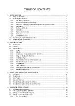
Page 2: ...2 3 3 Input Output Characteristics CH1 to CH11 6 2 3 4 Delay for Starting the Monitor 6 2 3 5 Input Signal Type 6 2 3 6 Determination Criteria of the Signal Level 7 2 3 7 Detection Reference Level 7...

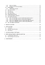
Page 3: ...en set to NORMAL and AUTO SWITCHING SWITCH FAULT 23 4 12 2 When set to NORMAL and AUTO SWITCHING DISABLED 24 4 12 3 When set to OVERRIDE and AUTO SWITCHING SWITCH FAULT 24 4 12 4 When set to OVERRIDE...

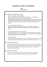
Page 4: ...wing terms and symbols that indicate necessary warnings and cautions used in this manual and on the product are there for safe operation Symbol The sections where this symbol is marked in this manual...

Page 5: ...ectric shock malfunction and accidents when the power is turned on Warnings on Power Line Make sure to connect only to the rated power line voltage Excessive voltage may cause fire Confirm the voltage...

Page 6: ...the Presence of Gasses Operating the instrument in or near the presence or storage locations of flammable or explosive gasses or fumes could cause an explosion or fire hazard Do not operate the instru...

Page 7: ...nts of this instruction manual please contact your local Leader agent Caution on Input Output Connectors Input connectors are rated with a maximum input Do not supply input exceeding the specification...

Page 8: ...Even during the warranty period Leader will charge a fee for repairs in the following cases 1 Repair of malfunction or damages resulting from fire natural calamity or improper voltage applied by the...

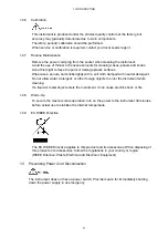
Page 9: ...rs Doing so can damage the instrument or device connected to it 1 2 4 Installation Do not use the instrument in the following environments High temperature environments Do not place the instrument und...

Page 10: ...soft cloth damped with neutral detergent Do not allow water detergent or other foreign objects to enter the instrument while cleaning If a liquid or metal object enters the instrument it can cause el...

Page 11: ...accidents that occur when these rails are not used Table 1 2 Recommended Slide Rails for the LT 4440 LT 444 one rail on each side Parts Number Maker Name C 203 16 IDEAL KC 251 16 TAKIGEN MODEL203 16 A...

Page 12: ...y combining the LT 4440 with the LT 443D or the LT 4400 Multiformat Video Generator 2 2 Features Input Output Provides 11 channels a single channel consists of PRIMARY input BACKUP input and OUTPUT ou...

Page 13: ...2 0 dB 200 MHz to 1 5 GHz Cross Talk 60 dB 0 to 10 MHz 30 dB 10 MHz to 1 0 GHz 20 dB 1 0 to 1 5 GHz 2 3 4 Delay for Starting the Monitor Select from two delay settings for starting the error monitor...

Page 14: ...ria Is Set to HIGH 1 HD SDI CH1 to CH6 only 505 to 713 mV 800 mV SD SDI 270 Mb s 505 to 713 mV 800 mV SD SDI 143 Mb s 505 to 713 mV 800 mV AES EBU digital audio 734 to 924 mV 1000 mV NTSC black burst...

Page 15: ...connector female Inch screws for fixing the shell 2 3 11 General Specifications Environmental Conditions Operating Temperature 0 to 45 C Operating Humidity 90 RH without condensation Spec Guaranteed...

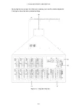
Page 16: ...CH DESCRIPTION 9 3 PANEL AND DIPSWITCH DESCRIPTION The front panel rear panel side panel and dipswitch section of the LT 4440 LT 444 are indicated below Figure 3 1 Front Panel Figure 3 2 Rear Panel Fi...

Page 17: ...3 PANEL AND DIPSWITCH DESCRIPTION 10 Removing the four screws from this cover enables you to set the internal dipswitch This figure shows the factory default settings Figure 3 4 Dipswitch Section...

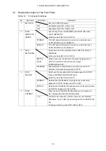
Page 18: ...NC SOURCE Switch used to manually switch the signal passed to OUTPUT between PRIMARY and BACKUP input 5 FAULT CHANNEL The LED of the channel on which a level error was detected keeps illuminating This...

Page 19: ...screws from this cover enables you to set the internal dipswitch 11 Signal selection switches CH1 to CH11 Dipswitches used to select the signal type for CH1 to CH11 12 Error detection level selection...

Page 20: ...When a level error is detected in the signal being passed to OUTPUT a switch is made to the other signal PRIMARY BACKUP 3 AUTO SWITCHING DISABLED Auto switching is not performed even when a level erro...

Page 21: ...ror detection low level selection switch VREF LOW No SW No Error Detection Level Selection All OFF Disable no error detection SW1 ON Select low level for NTSC Black Burst SW2 ON Select low level for P...

Page 22: ...U digital audio SW6 ON Select user defined level 1 common to high level and low level SW7 ON Select user defined level 2 common to high level and low level 12 SW8 ON Channels 1 6 Select high level for...

Page 23: ...PRIMARY and BACKUP must be of 75 impedance In addition the output from OUTPUT must be terminated at 75 Signals that are not selected by PRIMARY and BACKUP of SYNC SOURCE are terminated internally at 7...

Page 24: ...the setting and input signal are not matched erroneous operation will result This enables the error check of the NTSC BB input signal If the switch is set to OFF error check is not performed even whe...

Page 25: ...or large amount of noise is present in the signal erroneous operation may occur due the error detection being activated Figure 4 6 High level setting shows an example in which the detection level of t...

Page 26: ...w assumes that a C SYNC signal between 0 to 4V is applied to PRIMARY and BACKUP of CH7 1 Turn KEY LOCK OFF in advance 2 Prepare the signal source to be connected Signal level detection is possible in...

Page 27: ...on the instrument the power is ON when you connect the power plug When the power is applied the instrument starts up The front panel keys are disabled while the instrument is starting up The startup t...

Page 28: ...for approximately 1 minute KEY LOCK automatically turns ON and disables key operation 4 10 Output Signal Switching When the PRIMARY signal is selected When the BACKUP signal is selected Figure 4 11 Ou...

Page 29: ...or release procedure for BACKUP error as well as both PRIMARY and BACKUP errors is also the same Figure 4 13 Releasing the error of example 1 Example 2 When errors occur on multiple channels When an e...

Page 30: ...ATOR remains blinking and you do not press the RESET key When set to DISABLED auto switching is not performed even when a level error is detected in the signal being passed OUTPUT Use this setting if...

Page 31: ...set to NORMAL and AUTO SWITCHING SWITCH FAULT 4 12 3 When set to OVERRIDE and AUTO SWITCHING SWITCH FAULT Figure 4 19 OVERRIDE and AUTO SWITCHING SWITCH FAULT The operation of this combination is the...

Page 32: ...to PRIMARY Fault Normal Remains at PRIMARY Switch to BACKUP Remains at BACKUP Remains at BACKUP Normal Fault Remains at PRIMARY Remains at PRIMARY Remains at BACKUP Switch to PRIMARY NORMAL DISABLED...

Page 33: ...gnal is applied SYNC SOURCE switches between PRIMARY and BACKUP 3 SYNC SOURCE PRIMARY O Transmits a high signal when SYNC SOURCE is set to PRIMARY 4 SYNC SOURCE BACKUP O Transmits a high signal when S...

Page 34: ...ection example 1 2 6 I Connect a switch to apply a low signal Connect one side of the switch to the remote connector and the other side to ground 3 4 O 5 O Connect an LED so that it will light when a...

Page 35: ...s shown in Figure 6 1 However do not connect the signals until the setup is complete in order to prevent erroneous operation on the receiving device Figure 6 1 Connection example To the DIGITAL AUDIO...

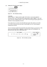
Page 36: ...l Set all the dipswitches for CH4 to CH11 to OFF 3 Set the error detection sensitivity Normally select VREF LOW 4 Set the MODE switch Normally set SW1 to Normal Operation and SW2 to FAST Mode 5 For th...

Page 37: ...to illuminate the OFF LED 2 Press the SYNC SOURCE key to illuminate the PRIMARY LED 3 Press the AUTO SWITCHING key to illuminate the SWITCH FAULT LED 4 Check that the PRIMARY and BACKUP LEDs of FAULT...

Page 38: ...ding to the type of signal used before starting operation Table 7 1 Factory default dipswitch settings Dipswitch Setup Item Description Dipswitch Setting MODE NORMAL MODE SW1 ON Startup time Approx 1...

Page 39: ...er Inlet stopper is supplied with the instrument Refer to the procedure below 8 1 Connecting the Power Cord 1 Insert the power cord connector into the AC inlet 2 Place the Cover Inlet stopper on top o...

Page 40: ...IPTION 33 8 2 Disconnecting the Power Cord 1 Press the levers on the Cover Inlet stopper with your fingers to release the lock 2 Remove the Cover Inlet stopper from the base 3 Disconnect the power cor...

Page 41: ...9 MAINTENANCE 34 9 MAINTENANCE The LT 4440 LT 444 is designed to operate stably under normal handling If you have questions regarding output calibration and service contact your local Leader agent...

Page 42: ...Following information is for Chinese RoHS only LT 444 4440 2006 2 28 SJ T11364 2006 Hazardous Substances in each Part Parts Pb Hg Cd Cr PBB PBDE SJ T11363 2006 SJ T11363 2006 Ver 2...

Page 43: ...LEADER ELECTRONICS CORP 2 6 33 Tsunashima Higashi Kohoku ku Yokohama 223 8505 Japan PHONE 81 45 541 2123 FAX 81 45 541 2823 http www leader co jp July 17 2012 Ver 4...

Reviews: