background image

1. INTRODUCTION 

1


1. INTRODUCTION 

Thank you for purchasing this LEADER instrument. To use this instrument safely, read this 
instruction manual thoroughly, and make sure that you know how to use the instrument 
properly. 


If some point about the operation of this instrument is still unclear after you have read this 
instruction manual, refer to the contact information on the back cover of the manual to contact 
LEADER, or contact your local LEADER agent. 
After you have finished reading this manual, keep it in a convenient place so that you can refer 
to it when necessary. 


1.1 

Scope of Warranty 

This LEADER instrument has been manufactured under the strictest quality control 
guidelines.  
LEADER shall not be obligated to furnish the following free services during the warranty 
period. 


Repair of malfunction or damages resulting from fire, natural calamity, or improper 
voltage applied by the user. 

Repair of an instrument that has been improperly repaired, adjusted, or modified by 
personnel other than a factory-trained LEADER representative. 

Repair of malfunctions or damages resulting from improper use. 

Repair of malfunctions caused by devices other than this instrument. 

Repair of malfunctions or damages without the presentation of a proof of purchase or 
receipt bill for the instrument. 


1.2 

Operating Precautions 

1.2.1 

Power Supply Voltage 


Confirm the voltage of the commercial power source before you connect the power plug to 
it. The operating voltage range is 90 to 250 VAC. Only use a power source that supplies a 
voltage within the operating voltage range and has a frequency of 50/60 Hz. 


1.2.2 

Maximum Allowable Input Voltage 


The maximum signal voltage that can be applied to the input connectors is indicated below. 
Do not apply excessive voltage to the connectors. Doing so may damage the instrument or 
lead to injury. 


Table 1-1    Maximum allowable input voltage 

Input Connector 

Maximum Allowable Input Voltage 

Channels 1 to 3 

±5 V 

Channels 4 to 10 

±1.5 V 

CH11 

0 V or +5 V 

Summary of Contents for LT 4441

Page 1: ...LT 4441 LT 4442 CHANGEOVER INSTRUCTION MANUAL...

Page 2: ...2 3 4 Signal Switching 5 2 3 5 Error Detection 6 2 3 6 Key Lock 7 2 3 7 External Control Connectors 7 2 3 8 General Specifications 7 3 NAMES AND FUNCTIONS OF PARTS 8 3 1 Front Panel 8 3 2 Rear Panel...

Page 3: ...5 2 Switching the Output Signal 21 4 5 3 Setting Automatic Signal Switching 22 4 5 4 Error Display and Resetting 23 5 EXTERNAL INTERFACE 24 5 1 Remote control Connector 24 6 CALIBRATION AND REPAIRS 2...

Page 4: ...If you have any questions about the contents of this manual please contact your local LEADER agent Symbols and Terms The following symbols and terms are used in this instruction manual and on the ins...

Page 5: ...r cord is damaged stop using it and contact your local LEADER agent Using a damaged power cord could lead to electrical shock or fire When removing the plug from the power outlet do not pull on the co...

Page 6: ...time remove the power plug from the outlet Operating Humidity Range Use this instrument in an environment whose relative humidity is 85 or less where there is no threat of condensation forming Also do...

Page 7: ...instrument fire or electric shock may result About the European WEEE Directive This instrument and its accessories are subject to the European WEEE Directive Follow the applicable regulations of your...

Page 8: ...r 2 Repair of an instrument that has been improperly repaired adjusted or modified by personnel other than a factory trained LEADER representative 3 Repair of malfunctions or damages resulting from im...

Page 9: ...with the external conductor 1 2 6 Rack Mounting If you are mounting this instrument on a rack be sure to provide additional support for the instrument If you only use the included rack supports to mou...

Page 10: ...can combine the LT 4441 4442 with multi format video generator LT 443D or LT 4400 to configure a system 2 2 Features I O Connectors The LT 4441 4442 is equipped with 11 sets of I O connectors a single...

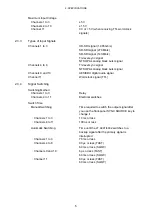
Page 11: ...nput connector TTL input 75 BNC connector Output Connectors Channels 1 to 10 10 output connectors 75 BNC connectors Channel 11 1 output connector 5 V CMOS output 75 BNC connector 2 3 2 I O Characteris...

Page 12: ...ignal Channel 11 Word clock signal TTL 2 3 4 Signal Switching Switching Method Channels 1 to 3 Relay Channels 4 to 11 Electrical switches Switch Time Manual Switching Time required to switch the outpu...

Page 13: ...mV Tri Level Sync Signal 337 to 476 mV 600 mV Word clock Signal TTL 1515 to 1907 mV 2400 mV When the Detection Level is HIGH 1 HD SDI Signal 1 485 Gb s 505 to 713 mV 800 mV SD SDI Signal 270 Mb s 505...

Page 14: ...Conditions Operating Temperature 0 to 45 C Operating Humidity Range 90 RH or less no condensation Optimal Temperature 5 to 40 C Optimal Humidity 85 RH or less no condensation Operating Environment Ind...

Page 15: ...er or not to automatically switch the output signal when an error occurs in the input signal Select SWITCH FAULT to switch the output signal automatically Select DISABLED to not switch the output sign...

Page 16: ...ut connector Normally apply the backup signal to this connector See section 4 4 Signal I O 9 REMOTE This is the remote control connector You can use this connector to perform functions such as configu...

Page 17: ...Top panel 12 DIP switch cover When you remove the four screws and the cover the DIP switches appear DIP switches are used to configure the LT 4441 4442 An explanation of the settings is printed on the...

Page 18: ...does not function when it is in this state Figure 4 1 Standby mode Leaving Standby Mode When the LT 4441 4442 leaves Standby mode the SYNC SOURCE PRIMARY AUTO SWITCHING SWITCH FAULT and KEY LOCK ON L...

Page 19: ...the Cover Inlet Stopper 1 Cover the power cord with the cover inlet stopper 2 Push the cover inlet stopper until you hear a click to attach it to the AC inlet 3 Check that the cover inlet stopper is...

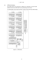
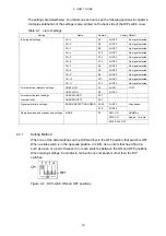
Page 20: ...hes on the top panel to configure the LT 4441 4442 To access the DIP switches first remove the DIP switch cover by unscrewing its four screws The following figure shows the DIP switches This figure sh...

Page 21: ...ed Input signal settings CH 11 S13 All OFF No signal selected VREF LOW S1 All ON Error detection reference settings VREF HIGH S2 All OFF LOW USER ADJUST1 RV1 Error detection level settings user define...

Page 22: ...osition If the settings do not match the signals that you apply or if you set two or more slide switches to the ON position for a single DIP switch errors will occur If you specify a signal with a DIP...

Page 23: ...Error detection reference settings Table 4 4 Error detection levels Error Detection Level 1 No Signal Type VREF LOW VREF HIGH SW1 NTSC analog black burst signal 180 to 227 mV 210 to 264 mV SW2 PAL an...

Page 24: ...to ON as shown in section 4 3 2 Input Signal Settings and then adjust the trimmer You can set up to two user defined error detection levels When you set SW6 to ON adjust RV1 When you set SW7 to ON adj...

Page 25: ...channel The factory default setting is high speed for all channels Figure 4 7 Signal switch time settings Table 4 6 Switch time Switch Time Remark No Channel High Speed OFF Low Speed ON SW1 Channel 4...

Page 26: ...u can use the SYNC SOURCE key to switch the output signal However this setting is valid when AUTO SWITCHING is set to DISABLED If AUTO SWITCHING is set to SWITCH FAULT even if you set the operation mo...

Page 27: ...Connect the output connector to the system s signal input connector The types of signals that you can apply to the LT 4441 4442 differ depending on the channel For details see Table 4 2 Types of input...

Page 28: ...igure 4 10 KEY LOCK 4 5 2 Switching the Output Signal Under SYNC SOURCE the LED that is lit shows which signal primary or backup is being transmitted from the output connectors The output signal setti...

Page 29: ...AUTO SWITCHING MODE Input Signal State Output Signal SYNC SOURCE Key Operation Output Signal SYNC SOURCE Key Operation Normal Remains PRIMARY Switches to BACKUP Remains BACKUP Switches to PRIMARY BAC...

Page 30: ...r display is shared between channels 1 to 11 The appropriate LED blinks when there is an error in any channel from channel 1 to 11 For example if errors occur in the primary signal of channel 1 and in...

Page 31: ...s not possible Set AUTO SWITCHING to SWITCH FAULT using keys to enable remote control 2 SYNC SOURCE I Each time a low signal is applied SYNC SOURCE switches between PRIMARY and BACKUP 3 SYNC SOURCE PR...

Page 32: ...nnection example 1 2 6 I Connect a switch to apply a low signal Connect one side of the switch to the remote connector and the other side to ground 3 4 O 5 O Connect an LED so that it will light when...

Page 33: ...accordance with the standards However because of factors such as parts wearing out over time the performance of the instrument may degrade To ensure stable performance we recommend that you have the...

Page 34: ...Following information is for Chinese RoHS only LT 4441 4442 2006 2 28 SJ T11364 2006 Hazardous Substances in each Part Parts Pb Hg Cd Cr PBB PBDE SJ T11363 2006 SJ T11363 2006 Ver 1...

Page 35: ...LEADER ELECTRONICS CORP 2 6 33 Tsunashima Higashi Kohoku ku Yokohama 223 8505 Japan PHONE 81 45 541 2123 FAX 81 45 541 2823 http www leader co jp July 17 2012 Ver 4...

Reviews: