background image


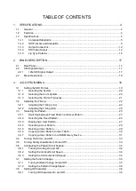
TABLE OF CONTENTS 

1.


SPECIFICATIONS ...................................................................................................... 4


1.1


General ...................................................................................................................................... 4


1.2


Features ..................................................................................................................................... 4


1.3


Specifications ............................................................................................................................. 5


1.3.1


Compliant Standards .......................................................................................................... 5


1.3.2


SDI Formats and Standards ............................................................................................... 5


1.3.3


Output Connectors ........................................................................................................... 12


1.3.4


SDI Video Output ............................................................................................................. 12


1.3.5


Lip Sync Patterns ............................................................................................................. 16


2.


PANEL DESCRIPTION ............................................................................................. 17


2.1


Rear Panel ............................................................................................................................... 17


2.2


SDI Signal Output .................................................................................................................... 17


2.2.1


12G-SDI Signal Output .................................................................................................... 17


2.3


Menu Operations ..................................................................................................................... 18


3.


12G OPTION MENU ................................................................................................ 19


3.1


Setting the SDI Format ............................................................................................................ 19


3.1.1


Selecting the System ....................................................................................................... 20


3.1.2


Selecting the Color System .............................................................................................. 20


3.1.3


Selecting the Frame Frequency ....................................................................................... 21


3.2


Adjusting the Timing ................................................................................................................ 22


3.2.1


Adjusting the Timing (Line) .............................................................................................. 22


3.2.2


Adjusting the Timing (Dot) ................................................................................................ 22


3.3


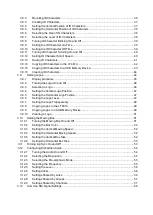
Selecting the Pattern ............................................................................................................... 23


3.3.1


Switching between Fixed Pattern and User Pattern ........................................................ 23


3.3.2


Selecting the Fixed Pattern .............................................................................................. 24


3.3.3


Displaying a User Pattern ................................................................................................ 27


3.3.4


Selecting a User Pattern .................................................................................................. 29


3.3.5


Deleting a User Pattern .................................................................................................... 29


3.3.6


Copying a User Pattern to the LT 4610 ............................................................................ 30


3.3.7


Copying a User Pattern to a USB Memory Device .......................................................... 31


3.4


Turning YCbCr On and Off ...................................................................................................... 33


3.5


Turning Safety Area Markers On and Off ................................................................................ 33


3.6


Configuring the Pattern Scroll Feature .................................................................................... 34


3.6.1


Turning Scrolling On and Off ............................................................................................ 34


3.6.2


Setting the Vertical Scroll Speed ...................................................................................... 34


3.6.3


Setting the Horizontal Scroll Speed ................................................................................. 34


3.7


Setting the Pattern Change ..................................................................................................... 35


3.7.1


Turning Pattern Change On and Off ................................................................................ 35


3.7.2


Setting the Pattern Change Speed .................................................................................. 35


3.8


Setting ID Characters .............................................................................................................. 36


3.8.1


Turning ID Characters On and Off ................................................................................... 36


Summary of Contents for LT 4610SER02

Page 1: ...LT 4610SER02 12G SDI Instruction Manual Thank you for purchasing Please carefully read this instruction manual and the included GENERAL SAFETY SUMMARY Please use the product safely...

Page 2: ...he Timing Dot 22 3 3 Selecting the Pattern 23 3 3 1 Switching between Fixed Pattern and User Pattern 23 3 3 2 Selecting the Fixed Pattern 24 3 3 3 Displaying a User Pattern 27 3 3 4 Selecting a User P...

Page 3: ...go 46 3 9 4 Setting the Vertical Logo Position 47 3 9 5 Setting the Horizontal Logo Position 47 3 9 6 Setting the Logo Level 47 3 9 7 Setting the Logo Transparency 48 3 9 8 Copying Logos to the LT 461...

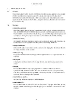
Page 4: ...ition on the display In addition ID characters can be displayed in a blinking state for checking whether the display has frozen Safety Area Markers 90 and 80 safety area markers can be overlaid on the...

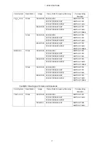
Page 5: ...esponding Standard YCBCR 4 2 2 10 bits 1280 720 60 59 94 50 30 29 97 25 24 23 98 P SMPTE ST 292 1 SMPTE ST 296 1920 1080 60 59 94 50 I SMPTE ST 274 SMPTE ST 292 1 30 29 97 25 24 23 98 P 30 29 97 25 24...

Page 6: ...9 94 50 I SMPTE ST 274 SMPTE ST 425 30 29 97 25 24 23 98 P 30 29 97 25 24 23 98 PsF 2048 1080 30 29 97 25 24 23 98 P SMPTE ST 425 1 SMPTE ST 2048 2 30 29 97 25 24 23 98 PsF 12 bits 1920 1080 60 59 94...

Page 7: ...RGB 4 4 4 10 bits 1920 1080 60 59 94 50 I SMPTE ST 274 SMPTE ST 372 SMPTE ST 425 30 29 97 25 24 23 98 P 30 29 97 25 24 23 98 PsF 2048 1080 30 29 97 25 24 23 98 P SMPTE ST 372 SMPTE ST 425 1 SMPTE ST...

Page 8: ...1920 1080 60 59 94 50 P SMPTE ST 274 SMPTE ST 425 3 2048 1080 60 59 94 50 48 47 95 P SMPTE ST 2048 2 SMPTE ST 425 3 3G DL 4K Video Signal Formats and Standards Division Transmission System Color Syst...

Page 9: ...24 23 98 P SMPTE ST 425 5 SMPTE ST 2048 1 YCBCR 4 4 4 10 bits 3840 2160 30 29 97 25 24 23 98 P SMPTE ST 425 5 SMPTE ST 2036 1 4096 2160 30 29 97 25 24 23 98 P SMPTE ST 425 5 SMPTE ST 2048 1 12 bits 3...

Page 10: ...PTE ST 425 5 SMPTE ST 2048 1 YCBCR 4 4 4 10 bits 3840 2160 30 29 97 25 24 23 98 P SMPTE ST 425 5 SMPTE ST 2036 1 4096 2160 30 29 97 25 24 23 98 P SMPTE ST 425 5 SMPTE ST 2048 1 12 bits 3840 2160 30 29...

Page 11: ...24 23 98 P SMPTE ST 2082 10 SMPTE ST 2036 1 YCBCR 4 4 4 10 bits 3840 2160 30 29 97 25 24 23 98 P SMPTE ST 2082 10 SMPTE ST 2036 1 4096 2160 30 29 97 25 24 23 98 P SMPTE ST 2082 10 SMPTE ST 2036 1 12...

Page 12: ...e 1 485 to 2 97 GHz 10 dB or more 2 97 to 6 GHz 7 dB or more 6 to 12 GHz 4 dB or more Rise and Fall Times 3G 135 ps 20 to 80 HD HD DL 270 ps 20 to 80 SD 0 4 ns to 1 5 ns 20 to 80 DC Offset 0 0 5V 1 3...

Page 13: ...a each for SD HD 2K and 4K File Format 24 bit full color bitmap format bmp After turning on the power perform a data memory transfer operation Data memory transfer takes time about 5 minutes for a 4K...

Page 14: ...88 cyan 88 green 88 blue 88 red 88 magenta 88 black 88 Speed Setting V H LOW MIDDLE HIGH Size Setting V H SIZE 1 to 5 Not available when the check field pattern is selected Pattern Scrolling Directio...

Page 15: ...The blinking display and scrolling can be used simultaneously Logo Mark Logo Mark Data 4 level monochrome data from level 0 to 3 Maximum Size 320 dots 240 lines QVGA size Number of Logo Marks That Can...

Page 16: ...CITT only the CS bit is switched Frequency SILENCE 400Hz 800Hz 1kHz Level 60 to 0 dBFs 1 dBFs steps Audio Click OFF 1 to 4 sec Audio including packets cannot be embedded when the check field pattern i...

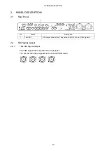
Page 17: ...ar Panel No Name Description 1 12G SDI SDI output connectors They output SD HD 3G and 12G signals 2 2 SDI Signal Output 2 2 1 12G SDI Signal Output Four SDI signals are output from the rear panel You...

Page 18: ...k Main unit Instruction Manual Chapter 7 4 BLACK menu Set the black signal Main unit Instruction Manual Chapter 8 5 SDI menu Set the SDI signal Main unit Instruction Manual Chapter 9 6 AES EBU menu Se...

Page 19: ...pecified on SDI1 On SDI2 to SDI4 different settings can be specified for groups of channels Note that for DUAL LINK SDI2 and SDI4 cannot be set because only two outputs will be available For QUAD LINK...

Page 20: ...L A 1920x1080 2048x1080 3G DL B DL 1920x1080 2084x1080 3G DL B DS 3840x2160 Square 3840x2160 2Sample 4096x2160 Square 4096x2160 2Sample 3G QL A 3840x2160 Square 3840x2160 2Sample 4096x2160 Square 4096...

Page 21: ...requency To select the SDI signal frame field frequency follow the procedure below Procedure 12G OPTION SDI1 FORMAT RATE Parameter 60P 59 94P default value 50P 48P 47 95P 30P 29 97P 25P 24P 23 98P 30P...

Page 22: ...elative to the reference signal at the line level follow the procedure below Procedure 12G OPTION SDI1 TIMING VERTICAL Parameter 561 default value 0 3 2 2 Adjusting the Timing Dot To adjust the SDI si...

Page 23: ...the and keys You can set SDI2 to SDI4 separately but the fixed pattern and user pattern cannot be displayed simultaneously 3 3 1 Switching between Fixed Pattern and User Pattern To switch between fix...

Page 24: ...epend on the SDI format as shown below Pattern SDI format Other than those on the right 720x487 SD 720x576 SD 3840x2160 4096x2160 COLOR BAR 100 Y Y Y Y Y 75 Y Y N Y Y MULTI 100 Y N N Y Y MULTI 75 Y N...

Page 25: ...3 12G OPTION MENU 25 100 75 MULTI 100 MULTI 75 MULTI I SMPTE EBU BBC...

Page 26: ...3 12G OPTION MENU 26 FLAT FIELD 100 FLAT FIELD 0 RED FIELD 100 GREEN FILED 100 BLUE FIELD 100 CHECK FIELD...

Page 27: ...LEADER bmp 1 Place the image file in the appropriate folder according to its image size in the USB memory device USB memory device LT4610_USER USER_PATTERN 4K bmp HD bmp SD bmp 2 On the COPY USB INT m...

Page 28: ...transfer it In the case of a 4K user pattern it takes about 5 minutes 5 Set the colorimetry and range when transferring a user pattern Select any values of your choice 6 Set whether to automatically...

Page 29: ...startup You can set this function in the procedure for transferring user patterns to memory An asterisk appears in front of the file name for the user pattern to be transferred using power on recall Y...

Page 30: ...ing folder structure is connected USB memory device LT4610_USER USER_PATTERN 4K HD SD Procedure 12G OPTION SDI1 PATTERN COPY USB INT To copy a user pattern follow the procedure below 1 Select the form...

Page 31: ...age files that are 720 487 or 720 576 3 3 7 Copying a User Pattern to a USB Memory Device To copy user pattern data from the LT 4610 to a USB memory device follow the procedure below The following men...

Page 32: ...R_PATTERN folder of the USB memory device USB memory device LT4610_USER USER_PATTERN 4K bmp HD bmp SD bmp 4K folder Image files that are 3840 2160 or 4096 2160 are stored HD folder Image files that ar...

Page 33: ...Turning Safety Area Markers On and Off To turn on and off the 90 marker 80 marker and 4 3 marker separately follow the procedure below If the 4 3 marker is off the 90 marker and 80 marker are displaye...

Page 34: ...ed To select the pattern scroll speed and direction follow the procedure below The unit is line field frame Setting a positive value scrolls upward and a negative value downward Procedure 12G OPTION S...

Page 35: ...on and off follow the procedure shown below If set to ON the pattern is switched automatically between the available color bar patterns for the current format Procedure 12G OPTION SDI1 VIDEO PATTERN...

Page 36: ...ETC menu is set to ON You can also set SDI2 to SDI4 separately 3 8 1 Turning ID Characters On and Off To turn ID characters on and off follow the procedure below Procedure 12G OPTION SDI1 VIDEO ID CH...

Page 37: ...enter in the middle of the ID character string characters after this character will disappear and you will not be able to edit them Procedure 12G OPTION SDI1 VIDEO ID CHARACTER SET Parameter Default s...

Page 38: ...ARACTER H POSI Parameter 0 to 1919 default value 0 3 8 6 Selecting the Size of ID Characters To set the size of ID characters follow the procedure below The size of x1 is 32 32 dot character Procedure...

Page 39: ...lt value 3 8 9 Setting the ID Character On Time To set the on time of ID character blinking follow the procedure below Procedure 12G OPTION SDI1 VIDEO ID CHARACTER BLINK ON TIME Parameter 1 to 9 defau...

Page 40: ...SDI1 VIDEO ID CHARACTER SCROLL ON OFF Parameter ON OFF default value 3 8 12 Setting ID Character Scroll Speed To set the ID character scroll speed and direction follow the procedure below The unit is...

Page 41: ...Enter a file name Select STORE The file name input menu appears This is the name assigned to the ID characters and is also the file name when the ID characters are copied to a USB memory device The c...

Page 42: ...USB memory device is connected Procedure 12G OPTION SDI1 VIDEO ID CHARACTER COPY USB INT To copy ID characters follow the procedure below 1 Select the copy destination in the LT 4610 Select from INT_1...

Page 43: ...is connected Procedure 12G OPTION SDI1 VIDEO ID CHARACTER COPY INT USB To copy ID characters follow the procedure below 1 Select the copy source in the LT 4610 Select ALL or from INT_1 to INT_4 2 Sel...

Page 44: ...haracters follow the procedure below 1 Select the ID characters you want to clear Select ALL or from INT_1 to INT_4 2 Select the OK 3 9 Setting Logos Under 12G OPTION SDI1 VIDEO LOGO you can set the l...

Page 45: ...ng of alphanumeric characters or underscore File format 24 bits 256 colors or 16 colors File size Up to 320 dots 240 lines width height LEADER bmp 2 Using the accompanying Logo App convert it to lg fo...

Page 46: ...Logo On and Off To turn the logo on and off follow the procedure below Procedure 12G OPTION SDI1 VIDEO LOGO ON OFF Parameter ON OFF default value 3 9 3 Selecting a Logo To select the logo to be displa...

Page 47: ...dinate at the left end of the logo The left end of the pattern is 0 Procedure 12G OPTION SDI1 VIDEO LOGO H POSI Parameter 0 to 1919 default value 0 3 9 6 Setting the Logo Level To set the logo intensi...

Page 48: ...select whether to make the area set to LEVEL0 transparent follow the procedure below Procedure 12G OPTION SDI1 VIDEO LOGO BACKGND Parameter ON The area is made transparent OFF The area is not made tr...

Page 49: ...d Procedure 12G OPTION SDI1 VIDEO LOGO COPY USB INT To copy logos follow the procedure below 1 Select the copy destination in the LT 4610 Select from INT_1 to INT_4 If there are already logos stored a...

Page 50: ...low 1 Select the copy source in the LT 4610 Select ALL or from INT_1 to INT_4 2 Select the OK If there are already logos with the same file names stored in the USB memory device they will be overwritt...

Page 51: ...ocedure below 1 Select the logos you want to clear Select ALL or from INT_1 to INT_4 2 Select the OK 3 10 Setting the Moving Box Under 12G OPTION SDI1 VIDEO MOVING BOX you can set the moving box This...

Page 52: ...the procedure below Procedure 12G OPTION SDI1 VIDEO MOVING BOX V SPEED Parameter LOW MIDDLE default value HIGH 3 10 4 Setting the Horizontal Moving Speed To set the moving speed follow the procedure...

Page 53: ...ible to measure the offset between the video signal and the audio signal that occurs in the transfer route for each channel For details see the instruction manual of the waveform monitor This is inval...

Page 54: ...group 1 SDI signal Link A HD DL 3G B only Group 1 Ch1 Ch2 Ch1 also possible Ch3 Ch1 also possible Ch4 Ch1 also possible Group 2 can also be set equal to group 1 Ch5 Ch6 Ch5 also possible Ch7 Ch5 also...

Page 55: ...4BIT 3 12 3 Selecting the Pre emphasis Mode To select the pre emphasis mode for the selected group follow the procedure below Procedure 12G OPTION SDI1 AUDIO LINK A LINK B G1 G2 G3 G4 EMPHASIS Paramet...

Page 56: ...el Follow the procedure below to set the insertion interval to a value other than OFF Procedure 12G OPTION SDI1 AUDIO LINK A LINK B G1 CH1 CH2 CH3 CH4 CLICK G2 CH5 CH6 CH7 CH8 CLICK G3 CH9 CH10 CH11 C...

Page 57: ...EQUAL TO G1 G3 EQUAL TO G1 G4 EQUAL TO G3 Parameter ON OFF default value 3 12 9 Settings Shared by Channels You can link the channel 2 setting to the channel 1 setting by following the procedure below...

Page 58: ...SDI2 and SDI3 settings to the SDI1 setting and the SDI4 setting to the SDI3 setting by following the procedure below to select ON When linked SDI2 to SDI4 cannot be set Procedure 12G OPTION SDI2 EQUA...

Page 59: ...ad office Sales Department Tel 81 45 541 2123 Fax 81 45 541 2823 Email sales leader co jp 2 6 33 Tsunashimahigashi Kohoku ku Yokohama shi Kanagawa 223 8505 Japan www leader co jp Apr 18 2018 Ver 2 Fir...

Reviews: