69
9. CINELITE DISPLAY
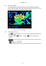
1. REF(f 0)
Luminance level when
REF_SET is pressed
2. Cursor
You can set up to three cursors. The f Stop value relative to the reference point is
displayed at each point.
3. P2-P1, P3-P1
f Stop difference
4. Coordinates
The cursor coordinates are indicated here with both line and sample numbers.
9.2
Procedure for Displaying the f Stop Display
The following example shows how to display luminance levels as f Stop numbers relative to
the luminance level of 18 % gray chart. Include an 18 % gray chart with the objects that you
are filming.
1. Press CINELITE.
2. Press
GAMMA to select a gamma correction table.
The default gamma correction value is 0.45, but you can also use a user-defined gamma
correction table that matches the gamma characteristics of the camera that you are
using. For details, see section 9.8, “Configuring User-Defined Correction Tables.”
3. Press
f_Stop DISPLAY.
4. Place the cursors over the 18 % gray area.
You can set the cursor to any measurement point from P1 to P3.
Reference 9.5, “Setting the Cursors”
5. Press
REF_SET.
The luminance level 18% gray becomes the reference value and is displayed as a
percentage in the bottom right of the display next to “REF(f 0).” The f Stop value for this
luminance level becomes 0.0.
6. Use the cursors to set the measurement points.
The f Stop value relative to 18% gray appears next to each cursor.
F•5
F•6
F•1
F•5

