76
9. CINELITE DISPLAY
9.9
Displaying Link Markers
To synchronize the markers on the vector screen and video signal waveform screen to
measurement points P1 to P3 and REF that you specify on the CINELITE screen, follow the
procedure below.
Markers cannot be displayed on the video signal waveform in the following situations.
• When SWEEP on the WFM menu is set to V
• When COLOR MATRIX on the WFM menu is set to COMPOSIT
Marker display will not work properly when waveforms are being displayed using an external
sync signal.
If P+V or P+V+W is selected, the measured values of the selected measurement point are
displayed in the lower left of the vector screen. For details on the measured values, see
section 12.4.5, “Turning Vector Markers On and Off.”
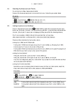
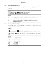
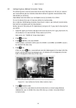
Procedure
Settings
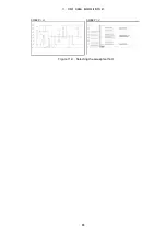
OFF:
P1 to P3 and REF are displayed only on the CINELITE screen.
P+V:
P1 to P3 and REF are displayed on the CINELITE and vector screens.
P+W:
P1 to P3 and REF are displayed on the CINELITE and video-signal-waveform
screens.
P+V+W:
P1 to P3 and REF are displayed on the CINELITE, vector, and
video-signal-waveform screens.
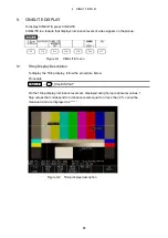
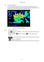
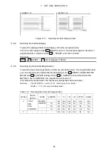
Figure 9-8 Displaying link markers
CINELITE → F•3 CINELITE ADVANCE: OFF / P+V / P+W / P+V+W

