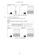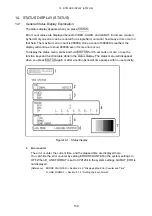
12. VECTOR DISPLAY (VECT)
144
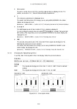
1 Error
counter
The error counter, the current time, and the elapsed time are displayed here. For
details, see section 14.1, “General Status Display Explanation.”
2 Y
The luminance signal level is displayed here.
The levels that fall outside of the range you set using LUMA ERROR in the status
display are displayed in red.
[Reference] LUMA
ERROR
→
Section 14.5.12, “Configuring Luminance Error Detection Settings”
3
G, B, and R
The GBR signal levels of the converted YC
B
C
R
signal are displayed.
You can change the signal order by setting F•1 SEQUENCE to RGB. The levels that
fall outside of the range that you set using GAMUT ERROR in the status display are
displayed in red.
[Reference] GAMUT
ERROR
→
Section 14.5.6, “Detecting Gamut Errors”
4 CMP
The pseudo-composite levels of the converted YC
B
C
R
signal are displayed. (The
blanking interval levels are not included.)
The levels that fall outside of the range you set using COMPOSIT GAMUT in the
status display are displayed in red.
[Reference] COMPOSIT
GAMUT
→
Section 14.5.9, “Detecting Composite Gamut Errors”
12.7.2
Changing the Signal Display Order
To set the order of the signals in the 5 bar display, follow the procedure below.
Procedure
VECT (press and hold)
→
F•5 5BAR SETUP
→
F•1 SEQUENCE
Settings
GBR:
The signals are displayed in this order: Y, G, B, R, CMP. This is the default
setting.
RGB:
The signals are displayed in this order: Y, R, G, B, CMP.
SEQUENCE = GBR
SEQUENCE = RGB
Figure12-18 5 bar signal orders

