4. BEFORE YOU BEGIN MEASURING
27
The maximum allowable voltage of the SDI input connectors is ±2 V. Do not apply excessive
voltage to the connectors. Doing so may damage the device or lead to injury.
4.3
Switching between SDI Signals (INPUT)
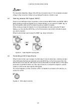
There are two SDI signal input connectors on the rear panel: INPUT SDI A and INPUT SDI B.
When viewing a single link signal in the 1-channel display, you can press the INPUT key on
the front panel to select which connector's signal you want to measure.
When viewing a single link signal in the 2-channel display and when using the 3D assist
display, you can press the INPUT key on the front panel to select which connector's signal
you want to transmit.
When the link format is set to dual, the INPUT key does not function.
Figure4-7 Switching SDI input signals
4.4
Transmitting an SDI Output Signal
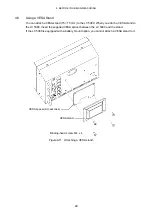
When the link format is set to single, the SDI output connector transmits a reclocked version
of the SDI signal that has been selected using the INPUT key on the front panel. When the
link format is set to dual, the SDI output connector transmits a reclocked version of the signal
received through INPUT SDI A. Use the output connector to transmit the signal to a picture
monitor or other device that supports SDI signals.
The output impedance of the connector is 75
Ω
. Terminate the connector of the device you
connect to at 75
Ω
.
Figure4-8 SDI output connector


