7. 3D ASSIST DISPLAY FEATURE
66
7.7.3
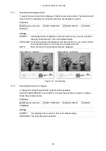
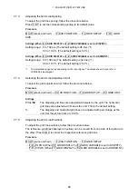
Adjusting the Grid Line Spacing
To adjust the grid line spacing, follow the procedure below.
Press F•D 1 to set the corresponding setting to its default value.
Procedure
MULTI (press and hold)
→
F•2 3D FUNCTION
→
F•4 GRID SETUP
→
F•D 1 GRID
SIZE
Settings (When F•1 GRID DISPLAY or F•2 GRID VARIABLE is set to DISPRTY.)
Setting range: 6 to 192 pix (The default setting is 96 pix) (*1)
0.3 to 10.0 % (The default setting is 5.0 %)
Settings (When F•1 GRID DISPLAY or F•2 GRID VARIABLE is set to HORIZONT.)
Setting range: 6 to 108 line (The default setting is 54 line) (*1)
0.6 to 10.0 % (The default setting is 5.0 %)
*1
The selectable range varies depending on the input signal. The values shown here are for a
1080i/59.94 input signal.
7.7.4
Selecting the Grid Line Adjustment Unit
To select the grid adjustment unit, follow the procedure below.
Procedure
MULTI (press and hold)
→
F•2 3D FUNCTION
→
F•4 GRID SETUP
→
F•3 GRID UNIT
Settings
PIX/LINE:
The disparity grid lines are adjusted with pixels as the unit. The horizontal
grid lines are adjusted with lines as the unit. This is the default setting.
%:
The disparity and horizontal grid lines are adjusted with percentage as the
unit. Set the picture frame to 100 %.
7.7.5
Adjusting the Grid Line Positions
To adjust the grid line positions, follow the procedure below.
The reference grid lines (displayed in yellow) can be moved from one side of the picture to
the other. Press F•D 2 to center the respective reference grid lines.
Procedure
MULTI (press and hold)
→
F•2 3D FUNCTION
→
F•4 GRID SETUP
→
F•D 2 H POS (When F•1 GRID DISPLAY or F•2 GRID VARIABLE is set to DISPRTY.)
→
F•D 2 V POS (When F•1 GRID DISPLAY or F•2 GRID VARIABLE is set to HORIZONT.)

