background image

5. SYSTEM SETTINGS (SYS) 

44


5.6 

Setting the Date and Time 

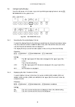
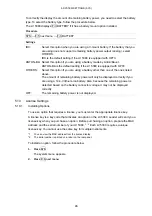
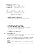
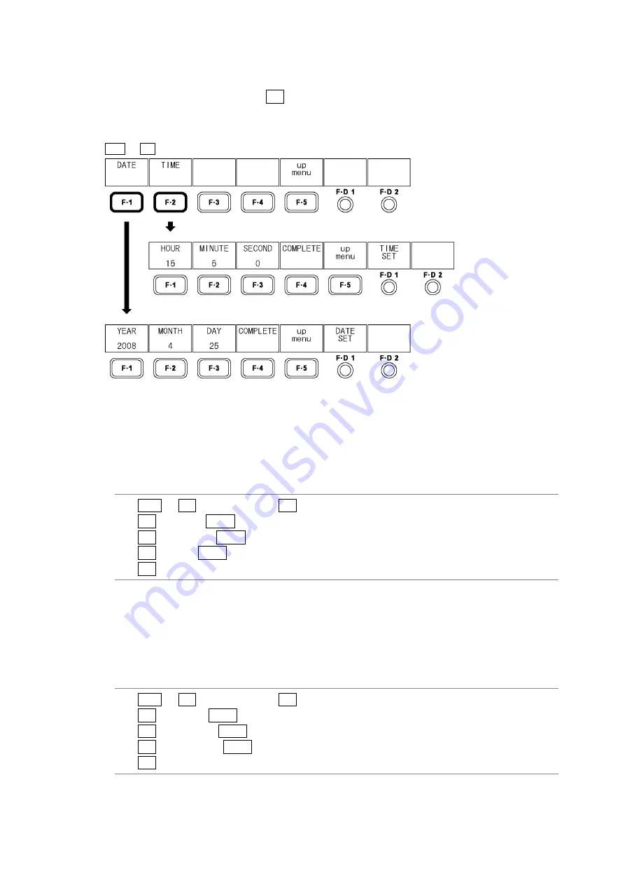
To set the date and time, access F•4 DATE&TIME in the system menu. 
The date and time that you set here will not be initialized even if you initialize the settings by 
following the procedure described in section 5.7.1, “Initializing the Settings.” 


SYS 

 F•4 DATE&TIME 


Figure5-8  DATE&TIME menu 


5.6.1 Setting 

the 

Date 

To set the date, follow the procedure below. 
The date that you set will be used when various kinds of data are saved to USB memory. 

Procedure 

1. SYS 

 F•4 DATE&TIME 

 F•1 DATE 

2. F•1 

YEAR 

 F•D 1 DATE SET 

(to set the year) 

3. F•2 

MONTH 

 F•D 1 DATE SET 

(to set the month) 

4. F•3 

DAY 

 F•D 1 DATE SET 

(to set the day) 

5.  F•4 COMPLETE 

(to confirm the date setting) 


5.6.2 Setting 

the 

Time 

To set the time, follow the procedure below. 
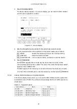
The time you set appears in the upper left of the screen next to TIME. 
It is also used when various kinds of data are saved to USB memory. 

Procedure 

1. SYS 

 F•4 DATE&TIME 

 F•2 TIME 

2. F•1 

HOUR 

 F•D 1 DATE SET 

(to set the hour) 

3. F•2 

MINUTE 

 F•D 1 DATE SET 

(to set the minute) 

4. F•3 

SECOND 

 F•D 1 DATE SET 

(to set the second) 

5.  F•4 COMPLETE 

(to confirm the time setting) 

Summary of Contents for LV 5380 OP72

Page 1: ...LV 5380 MULTI SDI MONITOR LV 5380 OP72 REMOTE TALLY LV 5380 OP73 BATTERY MOUNT IDX LV 5380 OP74 BATTERY MOUNT ANTON INSTRUCTION MANUAL...

Page 2: ...o Playback 7 2 3 3 Input Output Connectors 7 2 3 4 Control Connector 8 2 3 5 LCD 8 2 3 6 Screen Capture 8 2 3 7 Presets 8 2 3 8 Video Signal Waveform Display 9 2 3 9 Vector Display 10 2 3 10 5 Bar Dis...

Page 3: ...0 4 9 Basic Panel Operations 32 4 10 Displaying Menus 33 5 SYSTEM SETTINGS SYS 35 5 1 Setting the Input Format 35 5 1 1 Selecting a Link Format 35 5 1 2 Setting the Input Format Detection Method 36 5...

Page 4: ...etting the Histogram 56 6 8 1 Selecting the Display Format 56 6 8 2 Selecting the Channels To Display 57 6 8 3 Turning Y R G and B On and Off 57 6 9 User Defined Layout Settings 57 6 9 1 Displaying Us...

Page 5: ...htness 86 10 2 2 Setting the Contrast 86 10 3 Adjusting the Picture ADJUST 87 10 3 1 Switching between the Color and Monochrome Displays 87 10 3 2 Increasing the Chroma Gain 87 10 3 3 Turning RGB On a...

Page 6: ...Setting the Scale Intensity 110 11 4 Gain and Sweep Settings GAIN SWEEP 111 11 4 1 Switching between the Overlay and Parade Displays 111 11 4 2 Selecting the Sweep Method 112 11 4 3 Setting the Horizo...

Page 7: ...38 12 5 2 Displaying the Audio Meter 139 12 5 3 Selecting the Audio Meter Display Format 139 12 5 4 Displaying the Picture 140 12 6 Display Format Settings COLOR SYSTEM 141 12 6 1 Selecting the Displa...

Page 8: ...170 14 3 6 Setting the Data Dump Display Start Location 172 14 3 7 Saving a Data Dump to USB Memory 172 14 4 Phase Difference Measurement Settings EXT REF PHASE 174 14 4 1 Phase Difference Measuremen...

Page 9: ...Displaying a Tally Indication 189 15 1 6 Transmitting the Alarm Signal 190 16 APPENDIX 191 16 1 Menu Tree 191 16 1 1 Picture Menu 191 16 1 2 Video Signal Waveform Menu 194 16 1 3 Vector Menu 198 16 1...

Page 10: ...If you have any questions about the contents of this manual please contact your local LEADER agent Symbols and Terms The following symbols and terms are used in this instruction manual and on the inst...

Page 11: ...r in a high temperature environment could lead to fire Drastic changes in temperature such as might be caused by moving the instrument between two rooms with different temperatures can damage the inst...

Page 12: ...ded Period of Time If you will not use the instrument for an extended period of time remove the power plug and the battery If You Notice Something Wrong during Operation If you notice smoke fire a str...

Page 13: ...ents To clean the case panels and knobs use a soft cloth with mild detergent and wipe gently While cleaning make sure that foreign materials such as water and detergent do not enter the instrument If...

Page 14: ...idelines LEADER shall not be obligated to furnish free service during the warranty period under the following conditions 1 Repair of malfunction or damages resulting from fire natural calamity or impr...

Page 15: ...t your local LEADER agent The last memory feature is disabled The clock is initialized The contents of all presets are deleted To continually use these features we recommend that you replace the backu...

Page 16: ...I signal through channel A or B by pressing the INPUT key the output connector transmits the selected signal High Quality TFT LCD The LV 5380 achieves high picture quality by using an XGA TFT LCD 1024...

Page 17: ...5380 can display SDI signal data dump and error logs as well as the phase difference between the external sync signal and the SDI signal Time Code Display You can display LTC or VITC time codes ID Di...

Page 18: ...plays When you use an individual setting configuration for a particular display the settings for the other displays are not affected Last Memory Feature The LV 5380 backs up the current settings so th...

Page 19: ...0PsF 24 23 98 SMPTE 372 2048 1080 1080p 24 23 98 XYZ 4 4 4 2K 12 bits 1080PsF 24 23 98 SMPTE 428 1 9 Single Link Interface Format Color System Quantization 2 Scanning Frame Field Rates Compliant Stand...

Page 20: ...he selected SDI input signal Output Impedance 75 Output Voltage 800 mVp p 10 Output Return Loss 15 dB for 5 MHz to the serial clock frequency External Reference Input Input Signal Tri level sync or NT...

Page 21: ...ne screen capture can be stored in the internal memory Data Output Screen captures can be saved as bitmap files to USB memory or they can be saved in a file format that the LV 5380 can load Data Input...

Page 22: ...in 1 or 5 Variable Gain 0 2 to 2 0 Amplitude Accuracy 0 5 HD Frequency Response Y Signal 0 5 for 1 to 30 MHz CBCR Signal 0 5 for 0 5 to 15 MHz Low Pass Attenuation 20 dB at 20 MHz SD Frequency Respons...

Page 23: ...ment RGB or GBR Scale mV or Error Level Based on gamut error level composite gamut error level and luminance error level settings Line Select Displays the selected line Filter 1 MHz LPF or 2 8MHz LPF...

Page 24: ...nt Log Recording Capacity Up to 1000 events Description Records all events from start to finish Recorded Events Errors changes in input type time stamps etc Data Output Saved in text format to USB mem...

Page 25: ...F Composite Gamut Error Detects level errors that occur when component signals are converted to composite signals Detection Range NTSC Upper Limit 90 0 to 135 0 in 0 1 steps NTSC Lower Limit 40 0 to 2...

Page 26: ...onochrome video signal for the left eye and red is masked from the monochrome video signal for the right eye These signals are then combined Convergence Display A 50 offset is added to the difference...

Page 27: ...zontal Grid Lines 6 to 108 line 0 6 to 10 0 2 Grid Movement The disparity and horizontal grid lines can be moved separately Video Signal Waveform Display Waveform Display Color Video Signal for the Le...

Page 28: ...illuminate dimly The selected key lights more brightly Power Switch Turns the power on and off If power is removed when the switch is on the instrument will turn on when power is restored Last Memory...

Page 29: ...Specifications Control Connector Description Used to recall presets display tally indications switch input channels A or B and transmit the alarm signal Control Signal LV TTL level Input Active low lo...

Page 30: ...LV TTL Detection The alarm signal can be set to indicate INPUT SDI A errors INPUT SDI B errors or INPUT SDI A and B errors Tally Indication Description Displays tally information from the remote contr...

Page 31: ...onnector 1 IDX P V2 V plate Power Supply Input Range 10 to 18 VDC Remaining Battery Power Signal Input 0 to 5 VDC analog Battery Power Specifications Battery Output Voltage 10 to 18 VDC Rated Battery...

Page 32: ...it is available 2 6 3 Specifications Supported Batteries Gold mount batteries produced by Anton Bauer Input Connector 1 Anton Bauer QR GOLD mount Power Supply Input Range 10 to 18 VDC Remaining Batter...

Page 33: ...3 COMPONENT NAMES AND FUNCTIONS 20 3 COMPONENT NAMES AND FUNCTIONS 3 1 Front Panel Figure3 1 Front panel...

Page 34: ...menu Chapter 14 7 STATUS key Press Switches to status display mode Shows the display mode preset menu Press and hold Shows the status menu Chapter 14 8 MULTI key Press Switches between the single and...

Page 35: ...3 COMPONENT NAMES AND FUNCTIONS 22 3 2 Rear Panel Figure3 2 Rear panel Figure3 3 Rear panel with the battery mount option...

Page 36: ...3 VESA Mounting Holes VESA compliant 75 75 mm mounting holes 4 6 24 REMOTE OP72 Remote control connector Used to load presets transmit the alarm signal and perform other operations 5 5 15 1 25 Battery...

Page 37: ...t is produced when you connect the power cord to the LV 5380 1 Release the two tabs and open the ferrite core cover Figure4 1 Ferrite core attachment step 1 2 Attach the ferrite core approximately 5 m...

Page 38: ...ect anything to this pin The operating supply voltage range of this instrument s DC power supply is 10 to 18 V Do not apply a voltage that exceeds this range Doing so may damage the instrument or lead...

Page 39: ...wer supply to battery the LV 5380 may restart 4 2 Applying SDI Input Signals Apply an SDI signal to the SDI input connectors INPUT SDI A and INPUT SDI B Figure4 6 SDI input connectors The SDI input co...

Page 40: ...ress the INPUT key on the front panel to select which connector s signal you want to transmit When the link format is set to dual the INPUT key does not function Figure4 7 Switching SDI input signals...

Page 41: ...ernal reference input connectors to a cable with a characteristic impedance of 75 Figure4 10 Loop through To use an external sync signal set EXT REF to ON in video signal waveform vector or status dis...

Page 42: ...5380 When you attach a VESA stand to the LV 5380 insert the supplied VESA spacer between the LV 5380 and the stand If the LV 5380 is equipped with a battery mount option you cannot attach a VESA stand...

Page 43: ...SYS after the message Keylock Press SYS for 2sec appears in red in the bottom right of the display While the key lock is enabled a key symbol appears in the upper right of the display Disabling the Ke...

Page 44: ...ecode appears here You can set the timecode to LTC VITC or OFF Reference Section 5 4 1 Selecting the Timecode Display Format 4 Key Lock Indication This symbol appears when the key lock is enabled Refe...

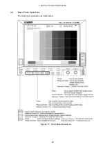
Page 45: ...4 BEFORE YOU BEGIN MEASURING 32 4 9 Basic Panel Operations The main panel operations are listed below Figure4 13 Basic Panel Operations...

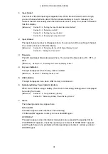
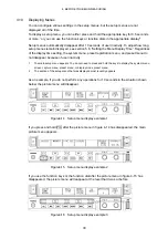
Page 46: ...do not disappear because of user inactivity 1 The main setup menu appears You do not need to press and hold the keys to display the system menu screen capture menu preset menu or display mode preset m...

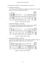
Page 47: ...ecting a pop up command Setting the Value Assigned to a Function Dial As an example to set F D 1 LISSAJOU INTEN in the figure below turn F D 1 If you press F D 1 LISSAJOU INTEN is set to its default v...

Page 48: ...or setting the input format and the composite display format appears SYS F 1 FORMAT Figure5 2 Format menu 5 1 1 Selecting a Link Format To select a link format follow the procedure below It takes appr...

Page 49: ...FORMAT SELECT Settings AUTO The input format is detected automatically This is the default setting MANUAL The input format must be set manually 5 1 3 Selecting i or PsF When the link format is set to...

Page 50: ...e signals F 3 D_LINK FORMAT for dual link signals Table 5 1 Input formats F 1 LINK FORMAT F 2 SCANNING F 3 FIELD FREQ FRAME FREQ D_LINK FORMAT 1080i default setting 60 59 94 default setting or 50 1080...

Page 51: ...C pseudo composite signals PAL All received SDI signals are converted into PAL pseudo composite signals 5 2 LCD Settings You can set the backlight shutoff time and brightness by accessing F 1 LCD in t...

Page 52: ...usting the Backlight Changing one of these values will also change the other value Procedure SYS F 2 DISPLAY F 1 LCD F D 1 BACK LIGHT Settings Setting range 1 to 32 The default setting is 17 5 3 Setti...

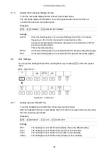
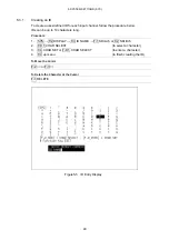
Page 53: ...p to 10 characters long Procedure 1 SYS F 2 DISPLAY F 3 ID NAME F 1 SDI Ach or F 2 SDI Bch 2 F D 1 CHAR SELECT to select a character 3 F 4 CHAR SET or F D 1 CHAR SELECT to enter a character 4 F 4 up m...

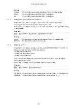
Page 54: ...vent log of the status display Procedure SYS F 2 DISPLAY F 4 INFORMATION F 1 TIME CODE Settings LTC The SDI input signal LTC timecode is displayed in the upper right of the screen This is the default...

Page 55: ...at the top of the screen in the center When the link format is set to dual the ID for channel A is displayed CHANNEL The input SDI signal channel name is displayed at the top of the screen in the cen...

Page 56: ...n error occurs in one of the items set to ON in the menu that appears when you press F 4 ERROR CONFIG in the status menu To set the polarity of the alarm signal follow the procedure below Procedure SY...

Page 57: ...of data are saved to USB memory Procedure 1 SYS F 4 DATE TIME F 1 DATE 2 F 1 YEAR F D 1 DATE SET to set the year 3 F 2 MONTH F D 1 DATE SET to set the month 4 F 3 DAY F D 1 DATE SET to set the day 5 F...

Page 58: ...nu F 1 INIT F 1 INIT YES 5 8 Setting the Menu Display Time To set the menu display time in five second steps follow the procedure below Setup menus automatically disappear after a set period of user i...

Page 59: ...ove The amount of remaining battery power will only be displayed correctly if you are using a 14 4 V lithium ion battery Also because the remaining power is detected based on the battery connector vol...

Page 60: ...ense key has been entered correctly and its corresponding option becomes usable The name of the option that has been added appears in the LICENSE LIST FAILED appears if the license key is not correct...

Page 61: ...conds or more or use the function keys and function dials while in the multi screen display MULTI press and hold Figure 6 1 Multi screen display menu The single screen display can show audio meters an...

Page 62: ...hosen when the link format is set to dual The line select feature the marker feature on the picture display and the field or frame display on the video signal waveform display cannot be used The signa...

Page 63: ...splayed on top of each other This is the default setting The SDI signal information and the error counter do not appear at the top of the screen The video signal waveform can be changed to the histogr...

Page 64: ...m and vector displays of channels A and B are arranged vertically WFM PIC The pictures of channels A and B are displayed with channel A on the left and channel B on the right The channel A video signa...

Page 65: ...6 MULTI SCREEN DISPLAY FEATURE MULTI 52 DISPLAY MODE P W H DISPLAY MODE P W V DISPLAY MODE W V V DISPLAY MODE WFM PIC DISPLAY MODE VEC PIC Figure 6 5 Multi screen display 2 channel display...

Page 66: ...of the screen and channel B is displayed on the right side of the screen OFF Channel A and channel B are displayed on top of each other This is the default setting WFM WIPE ON WFM WIPE OFF Figure 6 6...

Page 67: ...and hold F 4 DISPLAY FORM F 1 SUB ITEM Settings WFM The video signal waveform display appears This is the default setting HISTGRM The histogram display appears SUB ITEM WFM SUB ITEM HISTGRM Figure 6 7...

Page 68: ...ht eye are displayed on top of each other When F 2 WFM COLOR is set to RED CYAN only the parts where disparity exists are colored WFM FORM ALIGN WFM FORM MIX Figure 6 9 Video signal waveform display f...

Page 69: ...g the Display Format To select the histogram display format follow the procedure below Procedure MULTI press and hold F 4 DISPLAY FORM F 2 HISTGRM SETUP F 1 HISTGRM FORM Settings LUMA The histogram of...

Page 70: ...B On and Off When F 1 HISTGRM FORM is set to OVERLAY follow the procedure below to turn Y R G and B on and off separately You cannot turn all channels off Procedure MULTI press and hold F 4 DISPLAY F...

Page 71: ...YES The layout files are copied from the USB memory device to the LV 5380 To cancel the copy operation press F 3 COPY NO 4 Set F 1 INPUT MODE to SINGLE or DUAL 5 Set F 2 DISPLAY MODE to USER1 or USER2...

Page 72: ...MULTI press and hold F 2 3D FUNCTION Figure 7 1 3D FUNCTION menu 7 1 Selecting the Input Signal To select the input signal follow the procedure below Procedure MULTI press and hold F 5 3D INPUT FORMAT...

Page 73: ...ecause only the parts of the video that have disparity are colored CNVRGNCE A 50 offset is added to the difference between the monochrome video signal for the left eye and the monochrome video signal...

Page 74: ...7 3D ASSIST DISPLAY FEATURE 61 PICTURE FORM AGLPH CL AGLPH MO PICTURE FORM CNVRGNCE PICTURE FORM OVERLAY PICTURE FORM CHECKER PICTURE FORM WIPE PICTURE FORM FLICKER Figure 7 3 Picture display formats...

Page 75: ...edure MULTI press and hold F 2 3D FUNCTION F D 1 H VARIABLE Left right boundary line F D 2 V VARIABLE Top bottom boundary line 7 4 Configuring Wipe Display Settings When F 1 PICTURE FORM is set to WIP...

Page 76: ...rt the display press F 2 REVERSE on the 3D FUNCTION menu MULTI press and hold F 2 3D FUNCTION F 2 REVERSE Figure 7 6 REVERSE menu To invert the display of the picture and the video signal waveform for...

Page 77: ...GRID Grid lines are displayed You can use the grid to measure disparity DISPRTY Cursors are displayed You can perform detailed disparity measurements by setting the viewing environment MEASURE SELECT...

Page 78: ...Horizontal grid lines are displayed Use this option when you want to match the horizontal position of one camera or multiple cameras BOTH Both vertical and horizontal grid lines are displayed GRID DIS...

Page 79: ...7 4 Selecting the Grid Line Adjustment Unit To select the grid adjustment unit follow the procedure below Procedure MULTI press and hold F 2 3D FUNCTION F 4 GRID SETUP F 3 GRID UNIT Settings PIX LINE...

Page 80: ...displayed in light gray 7 8 Configuring Disparity Measurement Settings To configure the disparity measurement settings press F 4 DISPRTY SETUP on the 3D FUNCTION menu These settings are available when...

Page 81: ...for the left eye and the video signal for the right eye are displayed 6 Upper Limit This displays the upper disparity limits that were set on the PARAMETER display Depending on the cursor position the...

Page 82: ...LV 5380 are shown below Figure 7 12 Setting and measurement item names 7 8 2 Disparity Measurement Procedure To measure disparity follow the procedure below Before you begin this procedure set F 3 MEA...

Page 83: ...ange 0 1 to 250 0 m The default setting is 1 5 m 3 Under Upper Limit enter the upper limits for the measured values If at least one measured value exceeds its limit that you enter here NG is displayed...

Page 84: ...the screen Press F D 2 to move the cursor to approximately the center of the screen To Move the V Cursor It is useful to use the V cursor when you match the positions of the L and R cursors Also the l...

Page 85: ...Loading a Preset Press PSET and load the preset from the preset menu Display Mode Presets You can register up to five different sets of panel settings for each different display mode 2 When you use an...

Page 86: ...cters The key operations on the file name input display are as follows F 1 DELETE Deletes the character at the cursor F 2 Moves the cursor to the left F 3 Moves the cursor to the right F 4 CHAR SET En...

Page 87: ...g Presets 1 Press and hold PSET to display the preset registration menu 2 Press F 1 FULL PRESET to display a list of files 3 Turn F D 1 FILE SELECT to select the file number of the file you want to de...

Page 88: ...nter a file name using up to 16 characters The key operations on the file name input display are as follows F 1 DELETE Deletes the character at the cursor F 2 Moves the cursor to the left F 3 Moves th...

Page 89: ...es F 2 FUNCTION PRESET appears in the single screen display 3 Set F 1 FUNCTION PRESET to ON The default setting is OFF 4 Press the key of the display mode whose preset you want to load The display mod...

Page 90: ...SET 3 Press F 2 FUNCTION PRESET to display a list of files F 2 FUNCTION PRESET appears in the single screen display 4 Turn F D 1 FILE SELECT to select the file number of the file you want to delete 5...

Page 91: ...t have been saved to the LV 5380 to USB memory follow the procedure below If presets have already been saved to the USB memory they will be overwritten To cancel the copy operation press F 3 COPY NO T...

Page 92: ...eature Save it to USB memory as a BMP file Section 8 2 Saving Screen Capture Data to USB Memory Save it to USB memory as a BSQ file Section 8 2 Saving Screen Capture Data to USB Memory Save it to the...

Page 93: ...pressing F 1 REFRESH in the screen capture menu The screen capture menu will disappear if a certain period of time passes with no user activity To use the menu to make a setting press one of the func...

Page 94: ...ts to ON Both of the formats are set to ON by default BMP FILE The captured data is saved to the USB memory as a bitmap file You can view the saved file on a PC BSQ FILE The captured data is saved to...

Page 95: ...an This excludes parts of the 2 channel display and parts of the 3D assist display BOTH The input SDI signal and the captured data are displayed overlapping each other with their intensities halved Th...

Page 96: ...2 Press F 5 USB MEM RECALL F 5 USB MEM RECALL appears when USB memory is connected to the LV 5380 3 Turn F D 1 FILE SELECT to select the file that you want to display You can press F 3 DELETE here to...

Page 97: ...s PIC again or after a certain period of time passes with no user activity Figure10 1 Picture display 1 Error counter The error counter the current time and the elapsed time are displayed here For det...

Page 98: ...arkers Section 10 4 9 Setting User Marker Sizes 6 Safe title marker You can display a safe title marker according to the ARIB TR B4 or SMPTE RP 218 specification You can also set the marker to some ot...

Page 99: ...u 10 2 1 Setting the Brightness To set the picture brightness follow the procedure below If you press F D 1 the brightness will be set to its default value of 0 0 Procedure PIC press and hold F D 1 BR...

Page 100: ...e Displays To switch between the color and monochrome displays follow the procedure below This setting does not appear when the 3D assist display is in use Procedure PIC press and hold F 1 ADJUST F 1...

Page 101: ...low If you press F D 1 the gain will be set to its default value of 100 0 Procedure PIC press and hold F 1 ADJUST F 3 GAIN BIAS F 1 R SIGNAL when R is on F D 1 R GAIN F 2 G SIGNAL when G is on F D 1 G...

Page 102: ...onitor s Color Temperature To set the monitor s color temperature follow the procedure below Procedure PIC press and hold F 1 ADJUST F 4 COLOR TEMP Settings 6500K The monitor s color temperature is se...

Page 103: ...values will also change the other value This setting affects other displays in addition to the picture display Procedure PIC press and hold F 1 ADJUST F D 2 BACK LIGHT Settings Setting range 1 to 32 T...

Page 104: ...er is not displayed This is the default setting FRAME OFF FRAME ON Figure10 6 Displaying a frame marker 10 4 2 Displaying a Center Marker To display a center marker follow the procedure below The cent...

Page 105: ...et to 4 3 2 39 1 A 2 39 1 aspect marker is displayed This option cannot be selected when the input SDI signal is set to SD 16 9 A 16 9 aspect marker is displayed This option cannot be selected when th...

Page 106: ...safe title marker and user markers two types can be turned on and off separately Procedure PIC press and hold F 2 MARKER F 4 SAFETY ZONE F 1 STANDARD Settings ARIB ARIB TR B4 safe action and safe titl...

Page 107: ...is available when F 1 STANDARD is set to ARIB or SMPTE Procedure PIC press and hold F 2 MARKER F 4 SAFETY ZONE F 3 SAFE TITLE Settings ON A safe title marker is displayed OFF A safe title marker is no...

Page 108: ...Procedure PIC press and hold F 2 MARKER F 4 SAFETY ZONE F 2 USER ZONE1 when it is set to ON F D 1 USER ZONE1 H F D 2 USER ZONE1 V Settings Setting range 0 to 100 The default setting is 90 Setting Use...

Page 109: ...Section 10 6 1 Setting the Display Size PIC press and hold F 3 LINE SEL Figure10 11 LINE SEL menu 10 5 1 Displaying a Marker on the Selected Line To display a marker on the selected line follow the p...

Page 110: ...selection range can be set when the input format is set to interlaced or segmented frame Changing this setting will also change the video signal waveform display and vector display line selection rang...

Page 111: ...ls This setting cannot be chosen when D_LINK FORMAT is set to YC10bit X2 A single sample of the video signal is displayed with four pixels two horizontal and two vertical pixels on the screen The mark...

Page 112: ...FRM SIZE FUL SCRN Figure10 14 Picture display sizes 10 6 2 Setting the Display Position To set the picture position follow the procedure below This setting is available when F 1 SIZE is set to REAL X2...

Page 113: ...n 14 5 6 Detecting Gamut Errors COMPOSIT GAMUT Section 14 5 9 Detecting Composite Gamut Errors LUMA ERROR Section 14 5 11 Detecting Luminance Errors D_LINK FORMAT Section 5 1 4 Setting the Input Forma...

Page 114: ...5 Selecting the Audio Meter Display Format To select the audio meter display format follow the procedure below Configure 1st GROUP and 2nd GROUP in SDI GROUP in the audio display Changing this setting...

Page 115: ...ontally and displayed in 16 9 format 10 7 CINELITE Settings for the CINELITE option To configure the CINELITE settings press F 5 CINELITE on the picture menu or F 3 CINELITE on the multi screen displa...

Page 116: ...orms press WFM To display the video signal waveform menu press and hold WFM for 0 5 seconds or more or use the function keys and function dials while in the video signal waveform display The video sig...

Page 117: ...1 5 4 Switching to an External Sync Signal 5 Display format The video signal waveform display format YCbCr XYZ GBR YGBR RGB YRGB or COMPOSITE is displayed here Reference Section 11 6 1 Selecting a Dis...

Page 118: ...in the same way WFM press and hold Figure11 2 Video signal waveform menu 11 2 1 Setting the Horizontal Position To set the video signal waveform horizontal position follow the procedure below To retu...

Page 119: ...display format is PAL Reference COLOR MATRIX Section 11 6 1 Selecting the Display Format Composite display format Section 5 1 5 Setting the Composite Display Format Procedure WFM press and hold F 1 IN...

Page 120: ...one of seven options follow the procedure below Procedure WFM press and hold F 1 INTEN SCALE F 2 SCALE COLOR Settings WHITE The scale is displayed in white YELLOW The scale is displayed in yellow This...

Page 121: ...is set to RED CYAN in the 3D assist display this setting is not available If you press F D 2 the contrast will be set to its default value of MONOTONE Reference DISPLAY MODE Section 6 3 Selecting the...

Page 122: ...are displayed in the lower right of the screen in units of mV or as a percentage Press F D 1 to move marker 1 to the 0 0 mV position Press F D 2 to move marker 2 to the 100 0 mV position You cannot d...

Page 123: ...default value of 0 Procedure WFM press and hold F 1 INTEN SCALE F D 1 WFM INTEN Settings Setting range 128 to 127 The default setting is 0 11 3 8 Setting the Scale Intensity To set the scale intensity...

Page 124: ...ing between the Overlay and Parade Displays To switch between the overlay and parade displays follow the procedure below This setting is invalid when COLOR MATRIX is set to COMPOSIT Reference COLOR MA...

Page 125: ...annel display or 3D assist display If they are specified they are automatically changed to the line display Procedure WFM press and hold F 2 GAIN SWEEP F 2 SWEEP When the input format is interlaced or...

Page 126: ...he default setting H_2H Two lines are displayed at a time V_F1 Field 1 is displayed V_F2 Field 2 is displayed V_2V Single frames are displayed SWEEP H_1H single line display SWEEP H_2H double line dis...

Page 127: ...single frame display Figure11 11 When the input format is p in the parade display When the input format is progressive and MODE is set to OVERLAY Settings H_1H Single lines are displayed This is the d...

Page 128: ...EP MAG Settings 1 The video signal waveforms are displayed so that they fit in the screen This is the default setting 10 The video signal waveforms are magnified to 10 times the size of 1 at the cente...

Page 129: ...cal Gain To set the video signal waveform variable vertical gain follow the procedure below You can set the video signal waveform gain to a value between 0 2 and 10 by setting F 4 GAIN MAG and F D 1 G...

Page 130: ...ress and hold F 3 LINE SEL EXT REF Figure 11 15 LINE SEL EXT REF menu 11 5 1 Displaying the Waveform of the Selected Line To display the waveform of the selected line follow the procedure below Changi...

Page 131: ...display and vector display line selection ranges Procedure WFM press and hold F 3 LINE SEL EXT REF F 2 FIELD Settings the examples are for the setting ranges when the input format is set to 1080i 59 9...

Page 132: ...ngs DISPLAY To configure the display settings press F 4 DISPLAY in the video signal waveform menu You can set the video signal waveform display format channels filters the blanking display and thumbna...

Page 133: ...nd hold F 4 DISPLAY F 1 COLOR SYSTEM F 1 COLOR MATRIX Settings YCbCr Luminance and chrominance signals are displayed You cannot select this option when D_LINK FORMAT is set to XYZ12bit or GBR in the s...

Page 134: ...inance signal follow the procedure below The selected display format is indicated in the upper right of the display This setting is available when F 1 COLOR MATRIX is set to GBR or RGB Procedure WFM p...

Page 135: ...0 Pseudo composite display setup level 11 6 4 Turning YCBCR GBR or RGB Signal Components On and Off To turn individual channels in a YCBCR XYZ GBR or RGB signal on and off follow the procedure below Y...

Page 136: ...tting LOW PASS This filter is a low pass filter with the following frequency responses Attenuation of 20 dB or more at 20 MHz when the input SDI signal is HD Attenuation of 20 dB or more at 3 8 MHz wh...

Page 137: ...nd hold F 4 DISPLAY F 3 ARRANGE F 2 BLANKING Settings REMOVE Only the active period of the input SDI signal is displayed This is the default setting H VIEW The active period and the horizontal blankin...

Page 138: ...1 6 8 Selecting the Audio Meter Display Format To select the audio meter display format follow the procedure below Configure 1st GROUP and 2nd GROUP in SDI GROUP in the audio display Changing this set...

Page 139: ...n the video signal waveform display follow the procedure below Configure picture settings in the picture display Markers cannot be displayed Procedure WFM press and hold F 4 DISPLAY F 4 THUMBNAIL F 3...

Page 140: ...7 1 Displaying Cursors To display cursors follow the procedure below The REF cursor is displayed in blue and the DELTA cursor is displayed in green The measured value of DELTA REF is displayed in the...

Page 141: ...sing F D 1 changes the same setting To move both cursors separately Move the REF blue cursor with F D 1 REF and move the DELTA green cursor with F D 2 DELTA You can move both cursors simultaneously by...

Page 142: ...t to NTSC 714 mV 100 When COLOR MATRIX is set to COMPOSIT and the composite format is set to PAL 700 mV 100 R Measurements are made as percentages with the amplitude where REF SET is pressed set to 10...

Page 143: ...tors press VECT To display the vector menu press and hold VECT for 0 5 seconds or more or use the function keys and function dials while in the vector display The vector menu will disappear when you p...

Page 144: ...tor of the Selected Line Section 12 4 2 Selecting a Line 5 Sync signal EXT appears here when an external sync signal is being used Reference Section 12 4 4 Switching to an External Sync Signal 6 Thumb...

Page 145: ...tion 12 5 1 Switching between the Vector and 5 Bar Displays VECT press and hold F 1 INTEN SCALE Figure12 2 INTEN SCALE menu 12 2 1 Displaying the I and Q Axes To display the I and Q axes follow the pr...

Page 146: ...FM COLOR is set to This excludes the VEC PIC setting on the 2 channel display Reference WFM COLOR Section 11 3 3 Changing the Video Signal Waveform Color Procedure VECT press and hold F 1 INTEN SCALE...

Page 147: ...s Setting range 128 to 127 The default setting is 0 12 2 6 Setting the Scale Intensity To set the scale intensity follow the procedure below If you press F D 2 the scale intensity will be set to its d...

Page 148: ...d into component signals 2 63 for SD signals during pseudo composite display magnification that causes the I and Q signals of the SMPTE colorbar which has gone through pseudo composite conversion to l...

Page 149: ...EXT REF Figure12 6 LINE SEL EXT REF menu 12 4 1 Displaying the Vector of the Selected Line To display the vector of the selected line follow the procedure below Changing this setting will also change...

Page 150: ...orm display line selection ranges Procedure VECT press and hold F 3 LINE SEL EXT REF F 2 FIELD Settings the examples are for the setting ranges when the input format is set to 1080i 59 94 FIELD1 A lin...

Page 151: ...the procedure below You cannot show the 5 bar display when D_LINK FORMAT is set to XYZ12bit in the system settings or when DISPLAY MODE is set to VEC PIC in the 2 channel display Reference 5 bar disp...

Page 152: ...dio Meter Display Format To select the audio meter display format follow the procedure below Configure 1st GROUP and 2nd GROUP in SDI GROUP in the audio display Changing this setting will also change...

Page 153: ...n the vector display follow the procedure below Configure picture settings in the picture display Markers cannot be displayed Procedure VECT press and hold F 4 DISPLAY F 3 THUMBNAIL F 2 PICTURE Settin...

Page 154: ...display format is indicated in the lower right of the display There is no indication in the 5 bar display If you select COMPOSIT choose the composite display format NTSC or PAL by setting COMPOSIT FO...

Page 155: ...mat Section 5 1 5 Setting the Composite Display Format Procedure VECT press and hold F 5 COLOR SYSTEM F 3 SETUP Settings 0 No setup level is added This is the default setting 7 5 A setup level of 7 5...

Page 156: ...2 16 5BAR SETUP menu 12 7 1 General 5 Bar Display Explanation The 5 bar display appears when F 1 MODE is set to 5BAR In the 5 bar display the positive and negative peak levels are displayed simultaneo...

Page 157: ...t using GAMUT ERROR in the status display are displayed in red Reference GAMUT ERROR Section 14 5 6 Detecting Gamut Errors 4 CMP The pseudo composite levels of the converted YCBCR signal are displayed...

Page 158: ...mposite Display Format Procedure VECT press and hold F 5 5BAR SETUP F 2 SCALE Settings The scale units are set to and IRE This is the default setting mV The scale units are set to mV The scale values...

Page 159: ...in link A is measured 13 1 General Audio Display Explanation The audio display appears when you press AUDIO To display the audio menu press and hold AUDIO for 0 5 seconds or more or use the function...

Page 160: ...y Input Channels SINGLE LISSAJOU Section 13 2 2 Selecting Input Channels in the Single Lissajous Display Section 13 4 1 Selecting the Display Format section 13 3 Meter Settings METER SETUP 3 Lissajous...

Page 161: ...ECT To configure input channel settings press F 1 CHANNEL SELECT in the audio menu You can set the audio display and single lissajous display input channels and the headphone jack output channels AUDI...

Page 162: ...hone jack output channels from among the eight channels that you select The channels assigned to 1st GROUP and 2nd GROUP are listed below Audio display Thumbnails LAYOUT HORIZ1 Thumbnails LAYOUT HORIZ...

Page 163: ...four channels and the channels assigned to 2nd GROUP four channels The default settings are CH1 for L and CH2 for R 13 2 3 Selecting the Headphone Jack Output Channels To select the left and right he...

Page 164: ...follow the procedure below Levels that exceed the reference level are displayed in red and levels that are within the reference level are displayed in gray The reference level that you set here is als...

Page 165: ...o input preceding it 2 The amount of time it takes for the meter to show 40 dB when the application of a 20 dB 1 kHz sine wave signal stops 13 3 3 Selecting the Scale To select the type of meter scale...

Page 166: ...e meter reading for a 10 dB audio signal are shown below Table 13 2 Meter Settings F 1 REF LEVEL 20dB 18dB 12dB F D 1 F 3 SCALE TYPE A TYPE B TYPE A TYPE B TYPE A TYPE B HOLD TIME PEAK60dB 0 5 to 5 0...

Page 167: ...ssigned to 1st GROUP and 2nd GROUP using SDI GROUP are displayed The correlation meter in single lissajous mode indicates the phase difference between the two signals A reading of 1 indicates that the...

Page 168: ...the scale display format follow the procedure below Procedure AUDIO press and hold F 3 LISSAJOU SETUP F 2 FORM Settings X Y R is assigned to the X axis horizontal and L is assigned to the Y axis vert...

Page 169: ...e GAIN 1 GAIN AUTO Figure13 8 Setting the lissajous gain 13 4 4 Setting the Lissajous Curve Intensity To set the lissajous curve intensity follow the procedure below Procedure AUDIO press and hold F 3...

Page 170: ...LAY menu 13 5 1 Displaying the Picture To display the picture in the audio display follow the procedure below Configure picture settings in the picture display Markers cannot be displayed Procedure AU...

Page 171: ...nd hold Figure13 11 DISPLAY menu 13 6 1 Adjusting the Headphone Volume To adjust the headphone volume follow the procedure below If you press F D 1 the volume will be set to its default value of 0 The...

Page 172: ...the status menu press and hold STATUS for 0 5 seconds or more or use the function keys and function dials while in the status display The status menu will disappear when you press STATUS again or afte...

Page 173: ...hen the power is turned off Reference Section 5 7 1 Initializing the Settings section 14 6 1 Clearing Errors GAMUT_ERR The sum of the GAMUT COMP GAMUT and LUMA error counts is displayed here If the su...

Page 174: ...V 5380 do not match CRC will not appear if CRC is set to OFF or if the input signal is SD Reference Section 14 5 1 Detecting CRC Errors EDH EDH appears when the input SDI signal is SD An error is coun...

Page 175: ...An error is counted if the channel status bit of the input SDI signal s embedded audio has a CRC error However an error is not counted if the channel status bit is consumer Errors may be counted at th...

Page 176: ...mut Errors section 14 5 8 Configuring Gamut Error Detection Settings D_LINK FORMAT Section 5 1 4 Setting the Input Format COMP GAMUT An error is counted here when a gamut error is detected in the pseu...

Page 177: ...INPUT is set STATUS press and hold F 1 EVENT LOG Figure14 2 EVENT LOG menu 14 2 1 General Event Log Explanation To display the event log press F 1 EVENT LOG in the status menu Events include signal r...

Page 178: ...A or B are listed here 7 Input format The input formats when events occurred are indicated here If no signal was being received NO SIGNAL appears If the input format cannot be determined Unknown appea...

Page 179: ...pears in the event log and the status display STOP Event logging stops LOGGING STOPPED appears in the event log and the status display This is the default setting 14 2 4 Deleting the Event Log To dele...

Page 180: ...s according to the procedure in section 5 6 Setting the Date and Time Example 20080425150500 txt the order is year month day hour minute second The file structure in the USB memory is shown below USB...

Page 181: ...psed time are displayed here For details see section 14 1 General Status Display Explanation 2 LINE No The data dump display shows the data for a particular line The line that you select using F D 2 L...

Page 182: ...to scroll through the samples Reference SAMPLE SELECT Section 14 3 3 Scrolling through the Data Dump Display Samples 5 Data The data contained in the line samples is displayed here You can change the...

Page 183: ...e data dump display format follow the procedure below The types of display formats that you can select vary depending on the link format Procedure STATUS press and hold F 2 DATA DUMP F 2 DISPLAY When...

Page 184: ...link A are displayed This is the default setting LINK B The parallel converted data sequences of link B are displayed LINK A B Links A and B are combined and their parallel data sequences are displaye...

Page 185: ...to USB memory follow the procedure below You can view the saved data dump can on a PC This command appears when the LV 5380 has USB memory connected to it Regardless of the display and F D 1 SAMPLE S...

Page 186: ...040 200 0716 040 200 0717 040 200 0718 040 200 0719 040 200 Dual link YCbCr LINK A Dual link GBR LINK A B 2009 07 23 11 18 28 SDI DUAL LINK A REF INT FORMAT 1080i 59 94 DUAL LINE NUMBER 1 SAMPLE DATA...

Page 187: ...nc signal formats are listed below 1080i 60 1080i 59 94 and 1080i 50 1080p 30 1080p 29 97 1080p 25 1080p 24 and 1080p 23 98 1080PsF 30 1080PsF 29 97 1080PsF 25 1080PsF 24 and 1080PsF 23 98 720p 60 720...

Page 188: ...ure the phase difference between the input signal and an external sync signal Reference Section 14 4 6 Switching to an External Sync Signal 2 Error counter The error counter the current time and the e...

Page 189: ...4 2 Configuring a User Defined Phase Difference Setting Section 14 4 3 Using the Default Phase Difference Setting Section 14 4 4 Displaying the Phase Difference between Channels A and B Section 14 4...

Page 190: ...94 262 63 518 to 0 0 to 262 0 625i 50 312 63 962 to 0 0 to 312 0 14 4 2 Configuring a User Defined Phase Difference Setting To set the phase difference between the signals to 0 follow the procedure b...

Page 191: ...E F 3 REF SELECT Settings EXT The phase difference between an SDI signal and an external sync signal is displayed This is the default setting LINK A The phase difference between links A and B is displ...

Page 192: ...configure the input SDI signal video error audio error gamut error composite error and luminance error settings When D_LINK FORMAT is set to XYZ12bit in the system settings F 3 GAMUT ERROR is not dis...

Page 193: ...ou set this setting to ON the number of EDH errors appears next to EDH in the status display This setting is valid when the input SDI signal is SD Procedure STATUS press and hold F 4 ERROR CONFIG F 1...

Page 194: ...Section 12 7 1 General 5 Bar Display Explanation Procedure STATUS press and hold F 4 ERROR CONFIG F 3 GAMUT ERROR F 1 FILTER F 1 FILTER Settings ON The filter is turned ON This is the default setting...

Page 195: ...r display Setting the error detection upper limit An error is detected when the input SDI signal level exceeds the specified value If you press F D 1 the upper limit will be set to its default value o...

Page 196: ...e display format is NTSC This is the default setting PAL Composite gamut errors are detected Select this option when the composite display format is PAL OFF Composite gamut errors are not detected 14...

Page 197: ...press and hold F 4 ERROR CONFIG F 3 GAMUT ERROR F 3 COMPOSIT GAMUT F 4 AREA F D 1 VARIABLE Settings Setting range 0 0 to 5 0 The default setting is 1 0 14 5 11 Detecting Luminance Errors To detect lum...

Page 198: ...the level of the SDI input signal s luminance component goes below the specified value If you press F D 1 the lower limit will be set to its default value of 7 2 or 50 4 mV Procedure STATUS press and...

Page 199: ...ts pin assignments The locking screws are inch screws No 4 40UNC Do not apply voltage to the output pin Do not apply negative voltages or voltages that exceed 5 V to the input pins Figure15 1 Remote c...

Page 200: ...least 1 second before configuring the next setting Figure 15 2 Control timing 1 After a setting is made it may take about 3 seconds for the operation to finish If you configure subsequent settings be...

Page 201: ...IT BINARY Loaded Pin 9 Pin 8 Pin 7 Pin 6 Pin 5 Pin 4 Pin 3 Pin 2 Pin 6 Pin 5 Pin 4 Pin 3 Pin 2 Preset No P8 P7 P6 P5 P4 P3 P2 P1 P5 P4 P3 P2 P1 H H H H H H H L H H H H L 1 H H H H H H L H H H H L H 2...

Page 202: ...nnel B L L Selects channel A H H The selected channel is not switched 15 1 5 Displaying a Tally Indication Pin 12 TALLY1 and pin 13 TALLY2 of the remote control connector are used for the display of t...

Page 203: ...ON in the menu that appears when you press F 4 ERROR CONFIG in the status menu The alarm signal is a 3 3 V LV TTL level signal You can set the alarm signal polarity by setting ALARM POLARITY in the sy...

Page 204: ...ON OFF ON OFF ON OFF NORMAL UP CHROMA GAIN R SIGNAL F2 F4 50 0 0 0 50 0 ON OFF 50 0 0 0 50 0 OFF 16 9 14 9 13 9 OFF 14 9 13 9 4 3 2 39 1 SAFE ACTION FD1 FD1 FD2 4 ON OFF 12 B BIAS R GAIN F2 0 0 100 0...

Page 205: ...0 0 0 0 50 0 19 up menu LINE VARIABLE FD1 26 27 BRIGHT NESS 50 0 0 0 50 0 FD2 V POS FD2 CONTRAST FD1 BRIGHT NESS CINELITE 0 0 100 0 200 0 F5 22 SIZE FIT REAL GAMUT ERR DISP AUDIO METER OFF WHITE RED M...

Page 206: ...DI signal is interlaced or segmented frame 19 Appears when LINE SELECT is set to ON 20 Appears when in the system settings LINK FORMAT is set to SINGLE or D_LINK FORMAT is set to an option other than...

Page 207: ...3 SWEEP 18 20 19 6 F3 WFM F1 5 INTEN SCALE 3 HDV SD HDV SDV HD SD 1023 3FF 2 SCALE UNIT HDV SD HDV SDV HD SD 3FF F1 1 SCALE UNIT WHITE YELLOW CYAN GREEN MAGENTA RED BLUE H V H V_F1 V_F2 OVERLAY PARADE...

Page 208: ...POS LINE SEL EXT REF 21 31 SIGNAL DISPLAY F2 F4 up menu FIELD EXT REF ARRANGE F3 FILTER BLANKING BLANKING F1 5 F1 F1 32 F2 F5 F2 5 F4 DISPLAY F3 24 23 22 FILTER 28 29 up menu F5 F3 YGBR F2 0 7 5 up m...

Page 209: ...en DISPLAY MODE in the 2 channel display is set to WFM PIC or when WFM COLOR in the 3D assist display is set to RED CYAN 7 Appears when CURSOR is set to OFF or in the multi screen display 8 Appears wh...

Page 210: ...is set to SINGLE or D_LINK FORMAT is set to YC 26 Appears when in the system settings D_LINK FORMAT is set to XYZ12bit 27 Appears when in the system settings D_LINK FORMAT is set to GBR 28 Appears wh...

Page 211: ...up menu F2 F5 F5 SEQUENCE F1 F5 F5 COLOR BAR SCALE FD1 up menu F3 F1 DISPLAY F4 LINE SEL EXT REF FD1 GAIN VARIABLE 2 FD1 SCALE INTEN up menu FD1 FD2 F5 up menu 0 7 5 X1 X5 IQ MAG ON OFF FIELD1 FIELD2...

Page 212: ...in the multi screen display when INPUT MODE is set to DUAL 11 Appears when in the system settings LINK FORMAT is set to SINGLE or D_LINK FORMAT is set to an option other than YC10bit 12 Appears when...

Page 213: ...27 up menu VOLUME FD1 LISSAJOU INTEN THUMB NAIL PICTURE 4 SINGLE MULTI up menu 128 0 127 ON OFF X Y MATRIX X1 AUTO LISSAJOU MODE GAIN 0 5 5 0 HOLD TYPE A TYPE B PEAK60dB PEAK90dB AVERAGE 20dB 18dB 12d...

Page 214: ...SAV LINK A LINK B LINK A B 1 USB MEM STORE F4 up menu F5 EVENT LOG LOG STATUS F1 F1 FD1 MODE CLEAR F2 LOG MODE F3 OVER WR STOP F2 F1 2 DISPLAY DATA DUMP F2 up menu F5 3 DISPLAY F2 JUMP F3 1 USB MEM S...

Page 215: ...s set to DUAL or 2K 4 Does not appear appears when REF SELECT is set to LINK A 5 Appears when in the system settings LINK FORMAT is set to SINGLE and channel B is selected 6 Does not appear appears wh...

Page 216: ...SINGLE DUAL 3D ASIST 1 INPUT MODE 3 INPUT MODE F1 2 4 DISPLAY MODE F2 6 3D FUNCTION 5 DISPLAY MODE F2 F2 F1 AGLPH CL AGLPH MO CNVRGNCE OVERLAY CHECKER WIPE FLICKER 8 7 F2 F3 F3 OFF ON RIGHT OFF VERTIC...

Page 217: ...AUDIO F4 MULTI MENU F3 PIC F1 21 F4 DISPLAY FORM up menu F3 B F4 up menu F2 ON OFF F5 YRGB SELECT 29 F2 up menu F5 F5 Y F5 ON OFF ON OFF ON OFF G F3 8 20 F2 30 WFM WIPE F4 ON OFF H WIPE VARIABLE FD1 F...

Page 218: ...D DISPLAY or GRID VARIABLE is set to HORIZONT and GRID UNIT is set to PIX LINE This menu tree is for the 1080i 59 94 signal 14 Appears when GRID DISPLAY or GRID VARIABLE is set to HORIZONT and GRID UN...

Page 219: ...F4 F2 F3 FILE SELECT DISPLAY BMP FILE REAL HOLD BOTH F5 F2 F1 up menu BSQ FILE F1 F5 FD1 FILE SELECT up menu RECALL DELETE F3 DELETE NO F3 ON OFF ON OFF DELETE YES F1 1 Appears when USB memory is conn...

Page 220: ...UNCTION PRESET FILE SELECT FD1 FUNCTION PRESET F1 F2 F1 F4 F1 F3 1 F3 DELETE ON OFF F3 COMMENT INPUT PSET F2 FULL PRESET F1 OVER WR YES CHAR SET F4 up menu F5 DELETE NO F3 up menu F5 FILE SELECT FD1 F...

Page 221: ...F3 13 F3 50 GBR10bit GBR12bit YC10bit YC12bit XYZ12bit CHAR SELECT SINGLE DUAL 2K F5 LINK FORMAT F1 FD1 F1 FORMAT SELECT FD1 GBR12bit XYZ12bit BACK LIGHT AUTO NTSC PAL up menu 1 17 32 F4 F3 1 F2 1080i...

Page 222: ...F2 ON OFF CHAR SET CHAR SELECT F3 INPUT INFO up menu FORMAT F2 F4 ERROR COUNTER TIME CODE F3 F1 up menu ON OFF FD1 F4 up menu up menu F5 CH A CH B CH A B POSITIVE NEGATIVE F2 ALARM POLARITY F3 F2 F1...

Page 223: ...s set to YC10bit 7 Appears when LINK FORMAT is set to SINGLE and SCANNING is set to 1080i 8 Appears when LINK FORMAT is set to SINGLE and SCANNING is set to 1080PsF or 1080p 9 Appears when SCANNING is...

Page 224: ...the display formats in the 2 channel display in the multi screen display The waveforms can be displayed in a wipe display and the captured waveform colors match the displayed colors The following add...

Page 225: ...to the level meters in the audio display A thumbnail of the picture has been added to the status display An additional line has been added to the status dump display in the status display The functio...

Page 226: ...options OP73 BATTERY MOUNT IDX and OP74 BATTERY MOUNT ANTON are now supported Ver 1 8 The headphone output channels can now be set to any two channels The multi screen display now supports the simult...

Page 227: ...B SIGNAL 88 BACK LIGHT 39 90 BATTERY 45 BCH 180 BLANKING 124 BRIGHTNESS 86 C CAP 79 CENTER 91 CH CRC 181 CHANNEL SELECT 148 CHROMA GAIN 89 CHROMA UP 87 CINELITE 102 CLEAR 166 COLOR BAR 142 COLOR MATR...

Page 228: ...RIABLE 65 H H PHASE 175 H POS 66 99 105 H VARIABLE 62 H WIPE VARIABLE 63 HD LPF SELECT 181 HISTGRM FORM 56 HISTGRM SETUP 56 HOLD TIME 152 I I F SETUP 42 i PsF SELECT 36 ID NAME 39 INFORMATION 41 INIT...

Page 229: ...2 SDI GROUP 149 SEQUENCE 144 SETUP 69 122 142 SHADOW 92 SIGNAL DISPLAY 122 SINGLE LISSAJOU 150 SIZE 98 STANDARD 93 STATUS 159 SUB ITEM 54 SWEEP 112 SWEEP MAG 115 SYS 35 T THUMBNAIL 101 125 139 157 TIM...

Page 230: ...X X UNIT 129 Y Y UNIT 129 YGBR 121 YRGB 121 YRGB SELECT 57...

Page 231: ...Following information is for Chinese RoHS only LV 5380 2006 2 28 SJ T11364 2006 Hazardous Substances in each Part Parts Pb Hg Cd Cr PBB PBDE 5380 72 5380 73 5380 74 SJ T11363 2006 SJ T11363 2006 Ver 3...

Page 232: ...LEADER ELECTRONICS CORP 2 6 33 Tsunashima Higashi Kohoku ku Yokohama 223 8505 Japan PHONE 81 45 541 2123 FAX 81 45 541 2823 http www leader co jp May 8 2013 Ver 14 FW Ver 4 4...

Reviews: