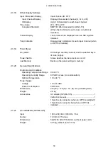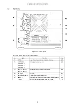
2. SPECIFICATIONS
17
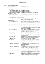
Inverted Display
Horizontal Inversion
Inverts the picture and video signal waveform (*2)
Vertical Inversion
Inverts the picture
Inverted Channel
Inverts video signal for the left eye and video signal for
the right eye separately
Grid Display
Description
Displays grid lines on the picture
Grid Type
Disparity, horizontal, both
Disparity grid width
6 to 192 pix (0.3 to 10.0 %) (*3)
Horizontal grid width
6 to 108 line (0.6 to 10.0 %) (*3)
Grid Movement
The disparity and horizontal grid lines can be moved
separately.
Video Signal Waveform Display
Waveform Display Color
Video Signal for the Left Eye Red
Video Signal for the Right Eye Syan
Display Format
Side by side, overlayed
Wipe Feature
L/R wipe
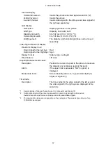
Disparity Measurement Feature
Description
Position the cursor at a point in the picture to measure
the disparity and luminance level at that point.
Alarm
If the upper limit is exceeded, “NG” (no good) is
displayed.
Measurable Items
Screen disparity (dots, cm, %), perceived depth (m),
angle of vergence (°)
Time Code
Description
The time codes for the video signal for the left eye and
the video signal for the right eye are displayed at the
same time.
*1
Select a pairing of channel A and channel C or channel B and channel D.
*2
Horizontal inversion of the video signal waveform occurs only during the video period.
Inversion cannot be performed on side-by-side or top-and-bottom signals.
*3
The pixel and line ranges vary depending on the input signal. The values shown here are for a
1080i/59.94 input signal.


