5. SYSTEM SETTINGS
42
5.5.2
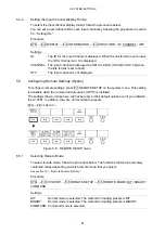
Selecting the Alarm Polarity
The alarm signal is transmitted from pin 14 (ALARM) of the remote control connector when
the LV 5381 internal temperature reaches or exceeds a specific value, when the fan is
broken, or when an error occurs in one of the items set to ON on the menu that appears
when you press F•4 ERROR CONFIG on the status menu.
To select the polarity of the alarm signal, follow the procedure below.
Procedure
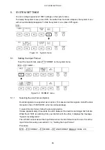
SYS
→
F•3 I/F SETUP
→
F•1 REMOTE SETUP
→
F•2 ALARM POLARITY: POSITIVE /
NEGATIVE
Settings
POSITIVE: An active-high signal is transmitted.
NEGATIVE: An active-low signal is transmitted.
5.5.3
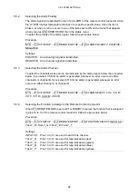
Selecting the Alarm Channel
To select the channels whose errors are indicated by the alarm signal, follow the procedure
below. If you select CH A/B, an alarm is generated whenever an error occurs on either
channel A or channel B. If you select CH C/D, an alarm is generated whenever an error
occurs on either channel C or channel D.
Procedure
SYS
→
F•3 I/F SETUP
→
F•1 REMOTE SETUP
→
F•3 ALARM SELECT: CH A / CH B /
CH C / CH D / CH A/B / CH C/D
5.5.4
Selecting the Function to Assign to the Remote Control Connector
When F•1 REMOTE MODE is set to BIT or BINARY, to select the function that is assigned
to pins 10 to 13 of the remote control connector, follow the procedure below.
Procedure
SYS
→
F•3 I/F SETUP
→
F•1 REMOTE SETUP
→
F•4 FUNCTION SELECT: INPUT CH /
TALLY_R / TALLY_G / TALLY_B / TALLY_Y
Settings
INPUT CH: Pins 10 to 13 are used to switch the channel.
TALLY_R:
Pins 10 to 13 are used for tally indications (red).
TALLY_G:
Pins 10 to 13 are used for tally indications (green).
TALLY_B:
Pins 10 to 13 are used for tally indications (blue).
TALLY_Y:
Pins 10 to 13 are used for tally indications (yellow).


