6. HDR DISPLAY (SER07)
94
6.1
Video Signal Waveform Display
On the video signal waveform display, scales and cursors for HDR signals can be displayed.
6.1.1
Scale Display
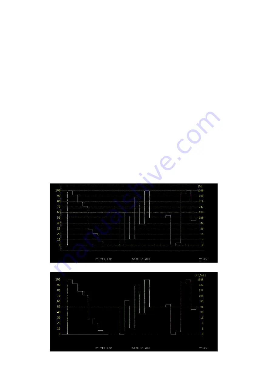
During HDR measurement, a scale corresponding to the HDR signal is displayed on the
right side of the video signal waveform.
The scale on the right side varies as follows depending on the STANDARD and SYSTEM
GAMMA parameters of the HDR tab.
• When STANDARD is HLG and
SYSTEM GAMMA is OFF: 0 to 100 [%] is displayed as 0 to 1200 [%].
SYSTEM GAMMA is ON:
0 to 100 [%] is displayed as 0 to 1000 [cd/m
2
].
• When STANDARD is PQ:
0 to 100 [%] is displayed as 0 to 10000 [cd/m
2
].
(If the scale unit is 1023,255 and 0 to 100 [%] is set to 64
to 940, 4 to 1019 is displayed as 0 to 10000 [cd/m
2
])
• When STANDARD is S-Log3 and
SYSTEM GAMMA is OFF: If 0 to 100 [%] is set to 64 to 940, 95 to 940 is displayed
as 0 to 2055 [%].
SYSTEM GAMMA is ON:
0 to 100 [%] is displayed as 0 to 3000 [cd/m
2
].
If GAIN VARIABLE is set to VARIABLE or if COLOR MATRIX is set to COMPOSITE, the
scale on the right side will not appear.
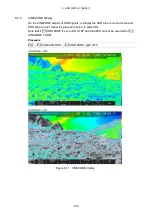
STANDARD = HLG, SYSTEM GAMMA = OFF
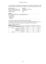
STANDARD = HLG, SYSTEM GAMMA = ON
Summary of Contents for LV 5480
Page 15: ...2 VIDEO SIGNAL WAVEFORM DISPLAY 7 SCALE UNIT HDV SDV SCALE UNIT HD SD SCALE UNIT 150 ...
Page 38: ...2 VIDEO SIGNAL WAVEFORM DISPLAY 30 COLOR MATRIX XYZ COLOR MATRIX GBR COLOR MATRIX RGB ...
Page 98: ...5 PICTURE DISPLAY 90 STATUS INFO ON Figure 5 34 Turning the information on and off ...


