2. VIDEO SIGNAL WAVEFORM DISPLAY
25
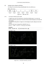
2.5.2
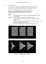
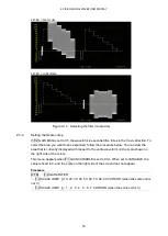
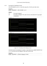
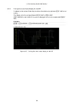
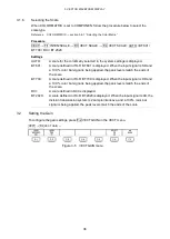
Setting the Line Selection Range
When F•1 LINE SELECT is set to ON and the input signal format is interlaced or segmented
frame, to set the line selection range, follow the procedure below.
Changing this setting will also change the selected line on the vector, picture, and status
(data dump) displays.
Procedure
WFM
→
F•4
LINE SEL →
F•2 FIELD: FIELD1 / FIELD2 / FRAME
Settings
FIELD1:
A line from field 1 can be selected. (Example: 1 to 563)
FIELD2:
A line from field 2 can be selected. (Example: 564 to 1125)
FRAME:
All lines can be selected. (Example: 1 to 1125)
2.6
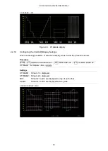
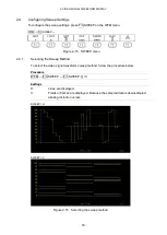
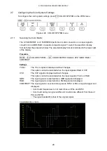
Configuring Cursor Settings
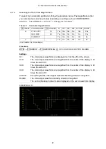
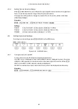
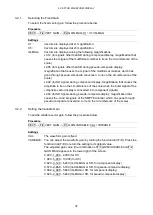
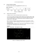
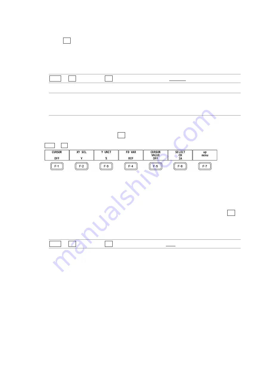
To configure cursor settings, press F•5 CURSOR on the WFM menu.
WFM
→
F•5
CURSOR →
Figure 2-23 CURSOR menu
2.6.1
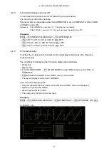
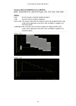
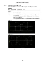
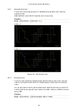
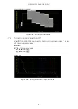
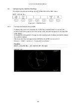
Turning Cursors On and Off
To turn cursors on and off, follow the procedure shown below.
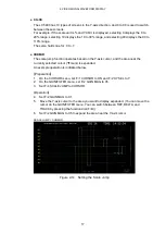
The REF cursor is displayed in blue, and the DELTA cursor is displayed in green. The value
of DELTA - REF appears as a measured value in the lower right of the screen. (When F•3 Y
UNIT is set to DEC or HEX, absolute values are displayed.)
If ON XY is selected, the X-axis cursors and Y-axis cursors are displayed simultaneously.
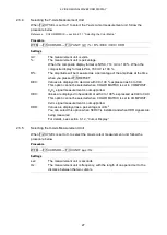
Procedure
WFM
→
F•5
CURSOR →
F•1 CURSOR: ON / ON XY / OFF
Summary of Contents for LV 5480
Page 15: ...2 VIDEO SIGNAL WAVEFORM DISPLAY 7 SCALE UNIT HDV SDV SCALE UNIT HD SD SCALE UNIT 150 ...
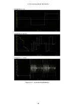
Page 38: ...2 VIDEO SIGNAL WAVEFORM DISPLAY 30 COLOR MATRIX XYZ COLOR MATRIX GBR COLOR MATRIX RGB ...
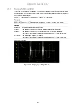
Page 98: ...5 PICTURE DISPLAY 90 STATUS INFO ON Figure 5 34 Turning the information on and off ...

