2. VIDEO SIGNAL WAVEFORM DISPLAY
29
2.7
Configuring the Color System Settings
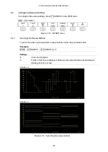
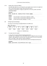
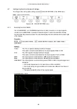
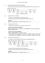
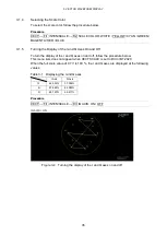
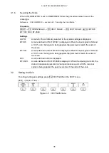
To configure the color system settings, press F•7 COLOR SYSTEM on the WFM menu.
WFM
→
F•7
COLOR SYSTEM →
Figure 2-26 COLOR SYSTEM menu
2.7.1
Selecting the Color Matrix
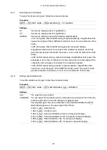
The LV 5490SER01 or LV 5490SER02 performs a matrix conversion on a input signal to
convert it into a GBR, RGB or pseudo-composite signal. To select the waveform display
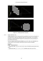
format, follow the procedure below. The selected display format is indicated in the lower right
of the display.
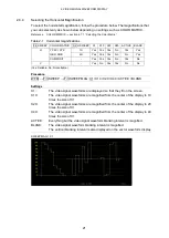
Procedure
WFM
→
F•7 COLOR SYSTEM
→
F•1 COLOR MATRIX: YCbCr / XYZ / GBR / RGB /
COMPOSIT
Settings
YCbCr:
The YC
B
C
R
signal is displayed without changes.
This option cannot be selected when the input signal is RGB or XYZ.
XYZ:
The XYZ signal is displayed without changes.
This option cannot be selected when the input signal is YC
B
C
R
or RGB.
GBR:
The input signal is converted into a GBR signal and displayed.
RGB:
The input signal is converted into a RGB signal and displayed.
COMPOSIT: The input signal is converted into a pseudo NTSC or PAL composite signal and
displayed.
• Color burst frequencies do not match those of PAL and NTSC.
• Color burst and sync signal widths and locations are different from those of
PAL and NTSC.
• The signal bandwidth is that of the original signal.
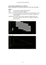
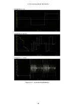
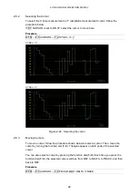
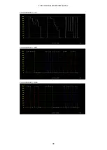
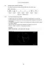
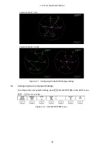
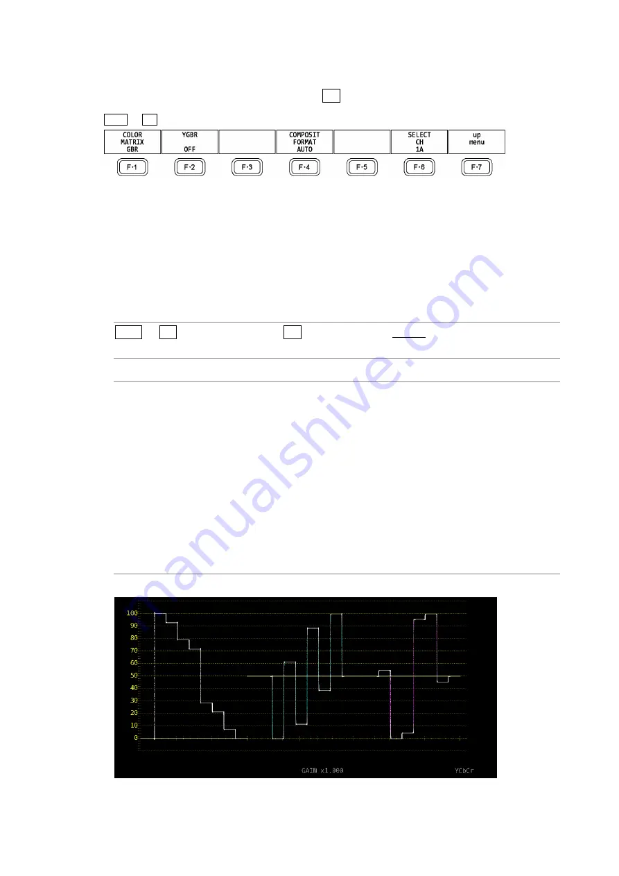
COLOR MATRIX = YCbCr
Summary of Contents for LV 5480
Page 15: ...2 VIDEO SIGNAL WAVEFORM DISPLAY 7 SCALE UNIT HDV SDV SCALE UNIT HD SD SCALE UNIT 150 ...
Page 38: ...2 VIDEO SIGNAL WAVEFORM DISPLAY 30 COLOR MATRIX XYZ COLOR MATRIX GBR COLOR MATRIX RGB ...
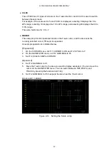
Page 98: ...5 PICTURE DISPLAY 90 STATUS INFO ON Figure 5 34 Turning the information on and off ...

