background image

2. SPECIFICATIONS 

21

2.3.16 

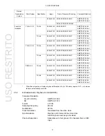
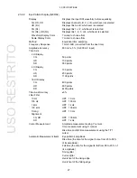
CIE Diagram Display (SER05) 

Display Standard 

CIE1931 (xy display), CIE1976 (u'v' display) 

Display Type 

Chromaticity diagram display, color temperature display 

Display Mode 

Chromaticity Diagram Display  Luminance display, color display 
Color Temperature Display 

Luminance display 

Colorimetry 

BT.601(525), BT.601(625), BT.709, DCI, BT.2020 

Clipping 

ON 

Clips negative values of the input signal to zero 

OFF 

Displays negative values of the input signal according to 
BT.1361 

Smoothing 

Displays by averaging data every two pixels 

Accuracy 

± 0.5 % 

Chromaticity Diagram Display Scale 

Triangle 

Select two from BT.601(525), BT.601(625), BT.709, DCI, 
and BT.2020 

Background 

Color sample, white background 

Sub Scale 

Color temperature curve, grid (0.1 steps), white point 
(D65), triangle name (each can be turned on or off) 

Cursor 

Displays the cursor position in coordinates 

Gamma 2.2, 

2.6 

2.3.17 

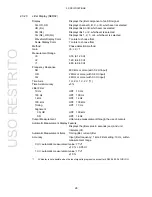
SDI Picture Display 

Quantization 8 

bits 

Display Sizes 

Reduced, actual size, ×2, full frame 

Quality Adjustment and Color Selection 

Brightness, contrast, gain, bias, chroma gain, 
monochrome display 

Frame Rate 

Converts the frame rate based on the LCD frame rate 
(60P, 59.94P, 50P) 

Aspect Marker 

3G (17:9 aspect ratio) 

16:9, 14:9, 13:9, 4:3, 2.39:1 

3G (16:9 aspect ratio), HD, HD (DL) 

17:9, 14:9, 13:9, 4:3, 2.39:1, AFD (*1) 

SD 

16:9, 14:9, 13:9, AFD (*1) 

Aspect Marker Format 

Line, shadow (99 levels), black 

Safety Marker Size 

ARIB TR-B4, SMPTE RP-218, or user-defined 

AFD Display (*1) 

Displays abbreviations for SMPTE 2016-3 standard AFD 
codes 

Line Select 

Marks the selected line 

*1 

Supports SD or HD. 

USO 

RESTRITO

Summary of Contents for LV 5490

Page 1: ...LV 5490 MULTI WAVEFORM MONITOR LV 5490SER01 SDI INPUT LV 5490SER02 SDI INPUT EYE LV 5490SER03 DIGITAL AUDIO LV 5490SER04 FOCUS ASSIST LV 5490SER05 CIE DIAGRAM INSTRUCTION MANUAL USO RESTRITO...

Page 2: ...TABLE OF CONTENTS USO RESTRITO...

Page 3: ...USO RESTRITO...

Page 4: ...USO RESTRITO...

Page 5: ...USO RESTRITO...

Page 6: ...f you have any questions about the contents of this manual please contact your local LEADER agent Symbols and Terms The following symbols and terms are used in this instruction manual and on the instr...

Page 7: ...rument has condensation within it wait for approximately 30 minutes before turning on the power Operating Humidity Range Use this instrument in an environment whose relative humidity is 85 RH or less...

Page 8: ...Pull from the plug Warnings Concerning Grounding The instrument has a ground terminal to protect the user and the instrument from electric shock Ensure that the product is properly grounded for safe o...

Page 9: ...mild detergent and wipe gently While cleaning make sure that foreign materials such as water and detergent do not enter the product If liquid or a metal object enters into the instrument fire or elec...

Page 10: ...pair of a product that has been improperly repaired adjusted or modified by personnel other than a factory trained LEADER representative 3 Repair of malfunctions or damages resulting from improper use...

Page 11: ...will appear and this last memory feature will no longer work To continually use the last memory feature we recommend that you replace the backup battery with a new one every five years after you purch...

Page 12: ...nals simultaneously Input Formats and Link Systems The following names are used for the input formats and link systems Multi link may be used as a collective term to refer to dual link and quad link T...

Page 13: ...with eye pattern 1 LV 5490SER03 DIGITAL AUDIO Digital audio I O LV 5490SER04 FOCUS ASSIST Focus assist LV 5490SER05 CIE DIAGRAM CIE diagram 1 The LV 5490 requires an LV 5490SER01 or LV 5490SER02 to be...

Page 14: ...screen can be output in SDI or DVI D from the monitor output connector The output signal can be displayed on an external LCD in full high definition resolution In addition an SDI signal received thro...

Page 15: ...isplays Other types of analysis displays are also available 16 channels of one SDI signal or 4 channels of four SDI signals can be displayed simultaneously Digital Audio I O SER03 The digital Audio I...

Page 16: ...Image Frame Field Frequency Scanning Compliant Standard YCBCR 4 2 2 10 bits 1920 1080 60 59 94 50 P SMPTE ST 274 SMPTE ST 425 1 2048 1080 60 59 94 50 48 47 95 P SMPTE ST 425 1 SMPTE ST 2048 2 12 bits...

Page 17: ...g Compliant Standard YCBCR 4 2 2 10 bits 1920 1080 60 59 94 50 P SMPTE ST 274 SMPTE ST 372 SMPTE ST 425 1 2048 1080 60 59 94 50 48 47 95 P SMPTE ST 372 SMPTE ST 425 1 SMPTE ST 2048 2 12 bits 1920 1080...

Page 18: ...Color System Quantization Image Frame Field Frequency Scanning Compliant Standard YCBCR 4 2 2 10 bits 1920 1080 60 59 94 50 I SMPTE ST 274 SMPTE ST 425 1 30 29 97 25 24 23 98 P 30 29 97 25 24 23 98 Ps...

Page 19: ...95 P SMPTE ST 425 5 SMPTE ST 2048 1 12 bits 3840 2160 30 29 97 25 24 23 98 P SMPTE ST 425 5 SMPTE ST 2036 1 30 29 97 25 24 23 98 PsF 4096 2160 30 29 97 25 24 23 98 P SMPTE ST 425 5 SMPTE ST 2048 1 30...

Page 20: ...SMPTE ST 425 5 SMPTE ST 2036 1 4096 2160 30 29 97 25 24 23 98 P SMPTE ST 425 5 SMPTE ST 2048 1 RGB 4 4 4 10 bits 3840 2160 30 29 97 25 24 23 98 P SMPTE ST 425 5 SMPTE ST 2036 1 4096 2160 30 29 97 25 2...

Page 21: ...3G A 3G B DL Four input signals consisting of 1A 1B 1C and 1D or four input signals consisting of 2A 2B 2C and 2D 3G B DS One input signal selected from 1A 1B 1C and 1D or one input signal selected f...

Page 22: ...me frequency 48P 47 95P Phase difference display using an external sync signal is not possible for the following formats 3G 720 30P 720 29 97P 720 25P 720 24P 720 23 98P Frame frequency 48P 47 95P 2 3...

Page 23: ...0 P Synchronization Synchronized with the LCD refresh rate free run or frequency synchronization with the external reference signal 1 Routing Outputs the SDI signal received through I O connectors 1A...

Page 24: ...us errors occur when the fan malfunctions or when the internal temperature is abnormal RS 422 485 Connector Custom order feature 2 3 8 Front Panel Display LCD Type 9 inch color TFT Resolution 1920 108...

Page 25: ...LV 5490 2 3 10 Frame Capture Function Captures frame data Indication Displays the captured frame data or superimposes the captured frame data over the input signal Media Internal memory RAM and USB me...

Page 26: ...23 98 PsF Table 2 11 3G DL video signal formats and standards Color System Quantization Image Frame Frequency Scanning Compliant Standard YCBCR 4 2 2 10 bit 3840 2160 30 29 97 25 24 23 98 P SMPTE ST 4...

Page 27: ...device or from a USB memory device to the LV 5490 1 The number of presets loaded from the remote control connector can be 8 or 60 2 3 13 Display Free Layout Function Freely arrange the windows shown...

Page 28: ...e signals and displays the result Line Select Displays the selected line Sweep Modes H V Color 7 colors to choose from Vertical Axis Gain 1 5 Variable Gain 0 2 2 0 Amplitude Accuracy 1 0 5 5 0 2 3G HD...

Page 29: ...7 colors to choose from Blanking Interval Masked Pseudo Composite Display Artificially converts component signals into composite signals and displays the result Line Select Displays the selected line...

Page 30: ...r sample white background Sub Scale Color temperature curve grid 0 1 steps white point D65 triangle name each can be turned on or off Cursor Displays the cursor position in coordinates Gamma 2 2 2 6 2...

Page 31: ...splayed Channels 8 or 16 channels Dynamic Range 60 dBFS 90 dBFS reference level 3 dB Meter Response Model TRUE PEAK PPM type I PPM type II VU Peak Hold Response Model TRUE PEAK PPM type I PPM type II...

Page 32: ...the number of times that the CRC of the channel status bits and the calculated CRC are different Code Violation Counts the number of times that the state of the input signal s biphase modulation is ab...

Page 33: ...ors DBN Error Detects audio packet continuity errors Parity Error Detects audio packet parity errors Embedded Position Error Detects the presence of audio in lines where it should not be embedded Samp...

Page 34: ...splay Details Analyzes and displays EDH packets and displays received CRC errors Display Format Text hexadecimal binary Payload ID Display Compliant Standard SMPTE ST 352 Display Details Analyzes and...

Page 35: ...pecification Method DID SDID Display Details Y C 1 If the reference signal is set to an external sync signal the measured phase may vary by 1 clock depending on the timing when the external sync signa...

Page 36: ...splay 3G 50 ps div HD 100 ps div SD 550 ps div 4 UI Display 3G 100 ps div HD 200 ps div SD 1100 ps div 16 UI Display 3G 400 ps div HD 800 ps div SD 4400 ps div Time Axis Accuracy 3 Jitter Filter 10 Hz...

Page 37: ...input HD 2 MHz or more with 0 2 UI input 3G 2 MHz or more with 0 3 UI input Time Axis 1 H 2 H 1 V 2 V 1 Time Axis Accuracy 3 Jitter Filter 10 Hz HPF 10 Hz 100 Hz HPF 100 Hz 1 kHz HPF 1 kHz 100 kHz HP...

Page 38: ...0 60 to 2 10 ns Fall Time 3G 40 to 140 54 0 to 189 0 ps HD 40 to 140 108 0 to 378 0 ps SD 40 to 140 0 60 to 2 10 ns Difference between the Rise and Fall Times 3G 40 to 140 20 to 70 ps HD 40 to 140 40...

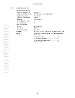
Page 39: ...t Indoors Elevation Up to 2 000 m Overvoltage Category II Pollution Degree 2 Power Requirements Voltage 90 to 250 VAC Frequency 50 60 Hz Power Consumption 150 W max Dimensions 223 W 172 H 360 D mm exc...

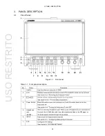
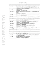
Page 40: ...nt Panel Figure 3 1 Front panel Table 3 1 Front panel description No Name Description 1 Handle 2 LCD 3 to 4 Power Switch 5 Headphone jack SER03 this jack the LV 5490 transmits the audio signal embedde...

Page 41: ...P 10 MULTI you like 11 PSET 12 WFM 13 AUDIO SER03 14 VECT 15 STATUS 16 PIC 17 EYE SER02 18 V POS 19 H POS Turn to adjust the horizontal position of the video signal waveform or other item Press to ret...

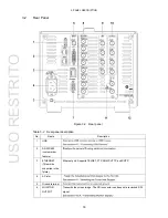
Page 42: ...ame Description 1 USB 2 RS 422 485 custom order feature 3 ETHERNET This will be supported in the future Ethernet port Supports TELNET FTP SNMP HTTP and SNTP 4 AC inlet 5 Ground terminal 6 MONITOR OUTP...

Page 43: ...connector Can be used to execute actions such as recalling preset settings 8 DIGITAL AUDIO INPUT OUTPUT SER03 Audio signal I O connectors Switch between input and output using system 9 SDI INPUT 10 S...

Page 44: ...stopper follow the procedure below Attaching the Cover Inlet Stopper 1 Cover the power cord with the cover inlet stopper 2 Push the cover inlet stopper until you hear a click to attach it to the AC in...

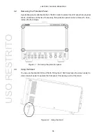
Page 45: ...es and the like If necessary this protection panel can be removed To do so remove the four screws Figure 4 1 Removing the protection panel 4 3 Using the Stand You can use the stand to tilt the LV 5490...

Page 46: ...lled in the LV 5490 If you want to obtain an option provide your local LEADER agent with the LV 5490 s MAC address see the LICENSE tab and serial number see the rear panel We will issue a license key...

Page 47: ...emory devices is connected a USB memory icon appears in the upper right of the screen You can save various types of data in a USB memory device This icon is normally green but it changes to red when t...

Page 48: ...nal Output Reference Input Through 2A to 2D output reclocked signals of the signals received through 1A to 1D Use the signals for monitoring For 3G DL the output signals are different as follows When...

Page 49: ...you can apply an external sync signal to display waveforms 1 Apply an external sync signal to an external sync signal input connector and then press EXT The LV 5490 determines the sync signal format...

Page 50: ...able 4 4 External sync signal formats SD HD Input Signal Format NTSC with 10 field ID 59 94Hz 1 NTSC 59 94Hz PAL 50Hz 1080 60I 1080 59 94I 1080 50I 1080 30PsF 1080 29 97PsF 1080 25PsF 1080 24PsF 1080...

Page 51: ...1 NTSC 59 94Hz PAL 50Hz 1080 60I 1080 59 94I 1080 50I 1080 30PsF 1080 29 97PsF 1080 25PsF 1080 24PsF 1080 23 98PsF 1080 30P 1080 29 97P 1080 25P 1080 24P 1080 23 98P 720 60P 720 59 94P 720 50P 1 If t...

Page 52: ...utput Use the signals for monitoring Table 4 6 Audio signal output INPUT CH MODE Group A Output Group B Output SDI 8ch The 8 channels from 1st GROUP and 2nd GROUP The 8 channels from 1st GROUP and 2nd...

Page 53: ...synchronization If you select internal synchronization you can also select the output format Reference SDI Routing Output In single link mode excluding 3G B DS in place of transmitting the LV 5490 scr...

Page 54: ...nction Key to Display a Menu Press one of the function keys to display the menu When you perform this operation the menu is displayed at the level that was displayed before it disappeared 4 9 2 Functi...

Page 55: ...the keys on the screen and the function menu You can change a value in the function menu by using the buttons to the right of FD the buttons to the right of the value or the wheel on the mouse The pre...

Page 56: ...ons Normally the function menus are used to configure the various settings However tab menus such as that shown below are displayed in some situations This section explains how to operate the tab menu...

Page 57: ...settings from all the tabs and return to the screen that is one level up 4 9 5 Setting the Key Lock You can prevent unintentional operations on the LV 5490 by enabling the key lock The key lock disab...

Page 58: ...rement screen explanation Table 4 8 Measurement screen explanation No Name Description 1 TEMPERATURE 2 ERROR Appears when an input signal error occurs 1 To configure error detection settings use STATU...

Page 59: ...ture increases FAN ALARM appears when a fan error occurs If either of these alarm appears immediately turn the power off and then check for problems with the operating environment If this alarm appear...

Page 60: ...for each of the different input signal formats 5 1 1 Notes This section provides notes common to all input signal formats INPUT FORMAT If the input signal or payload ID is not appropriate for the set...

Page 61: ...you want to set use 6 SELECT CH on each measurement screen A portion of the settings such as ERROR CLEAR on the STATUS menu are shared by all channels F 6 SELECT CH Measurement menus with an exceptio...

Page 62: ...Figure 5 2 SDI IN tab 2 If the input signal is HD or 3G set the payload ID Select Use or Not Use If you select Not Use specify the following settings 3 Press Select Input to apply up to eight signals...

Page 63: ...6 Press INPUT to select the channels you want to measure First press 7 DISPLAY to select whether to measure a single channel SINGLE or multiple channels SIMUL Next press 5 INPUT GROUP to select wheth...

Page 64: ...yload ID Select Use or Not Use If you select Not Use set i PsF Select Even if Use is selected if a 3G B DL signal is applied the LV 5490 will detect is as a 3 Press Select Input to apply up to eight s...

Page 65: ...to 2A to 2D Figure 5 8 SDI input connectors 6 Press INPUT to select the channels you want to measure First press INPUT GROUP to select whether to measure 1A to 1D 1 or 2A to 2D 2 This does not appear...

Page 66: ...5 10 SDI IN tab 2 Set the payload ID Select Use or Not Use If you select Not Use set i PsF Select Color System and Pixel Depth 3 Select Input to apply up to four signals 1A 1B 1C 1D 2A 2B and 2C 2D Se...

Page 67: ...tors 6 Press INPUT to select the channels you want to measure First press DISPLAY to select whether to measure a single channel SINGLE or multiple channels SIMUL Next press INPUT GROUP to select wheth...

Page 68: ...ayload ID Select Use or Not Use If you select Not Use set Division Even if Use is selected if a 3G B DL signal is applied the LV 5490 will detect is as a 3 Press Select Input to apply up to four signa...

Page 69: ...t apply signals to 2A to 2D Figure 5 16 SDI input connectors 6 Press INPUT to select the channels you want to measure First press 5 INPUT GROUP to select whether to measure 1A to 1D 1 or 2A to 2D 2 Th...

Page 70: ...HD Quad Link SYS F 1 SIGNAL IN OUT Figure 5 18 SDI IN tab 2 Press NEXT TAB and then set SDI In Out BNC Select Input to apply up to two signals 1A to 1D and 2A to 2D Select Output to apply up to one s...

Page 71: ...s selected in step 2 do not apply signals to 2A to 2D Figure 5 20 SDI input connectors 5 Press INPUT to select the channels you want to measure Press INPUT GROUP to select whether to measure 1A to 1D...

Page 72: ...OUT Figure 5 22 SDI IN tab 2 Set the payload ID Select Use or Not Use If you select Not Use set Division Color System and Pixel Depth 3 Select Input to apply up to two signals 1A to 1D and 2A to 2D S...

Page 73: ...tput is selected in step 3 do not apply signals to 2A to 2D Figure 5 24 SDI input connectors 6 Press INPUT to select the channels you want to measure Press 5 INPUT GROUP to select whether to measure 1...

Page 74: ...nal Waveform Display To display video signal waveforms press WFM The available features include line select display which displays the waveform of the selected line RGB display and pseudo composite di...

Page 75: ...display and focus assist display SER04 Figure 5 28 Picture display 5 2 4 Audio Display SER03 To show the audio display press AUDIO If SER03 is not installed the AUDIO key is disabled The available fea...

Page 76: ...data dump display Figure 5 30 Status display 5 2 6 Eye Pattern Display SER02 To show eye patterns press EYE If SER02 is not installed the EYE key is disabled You can also show jitter by switching MOD...

Page 77: ...1 LAYOUT SELECT To set each measurement screen use 2 MULTI WFM to 7 MULTI EYE USER 1 The vector video signal waveform status and picture are displayed in four divided screens Figure 5 32 Multi displa...

Page 78: ...reen and the video signal waveform and picture are displayed as thumbnails Figure 5 34 Multi display USER 3 USER 4 The picture video signal waveform and vector are displayed top to bottom This is suit...

Page 79: ...the front or rear panel USB port The layout that you specify will not be initialized even if you initialize the LV 5490 To initialize LAYOUT INIT YES on the SYS menu The entire layout is initialized...

Page 80: ...ulti display User 1 in the following manner a Display the layout screen b Change TIME in the upper right of the screen to DATE c Superimpose the vector on the picture d Add audio e Add TIME to the sta...

Page 81: ...ME This indicates that the TIME item is selected 4 Click DELETE The TIME item is deleted 5 On the Sub tab click DATE The DATE item appears 6 Place the DATE item in the area where the TIME item was dis...

Page 82: ...re 8 Place the VECT item on top of the picture Resize as necessary d Add audio 9 Click AUDIO on the Main tab The AUDIO item appears You can place an AUDIO item even if SER03 is not installed but the m...

Page 83: ...ow by dragging and close it by clicking X in the upper right of the window If you close it you can redisplay it by double clicking in the layout screen 2 Item Displays the item selected on the Main or...

Page 84: ...elect the display format for simul mode Display Mode applies to the entire screen Style applies to the selected item If Display Mode is set to TILE or if the selected item is AUDIO or EYE Style cannot...

Page 85: ...changes depending on Display Mode as follows Figure 5 41 Single input mode When Display Mode Is NORMAL The screen is divided by channel within each item Select the division format with Style TILE til...

Page 86: ...maticity diagram SER05 will not be displayed properly if the VECT item is overlapping other items AUDIO Click this after selecting the display mode on the AUDIO tab to show the audio display If SER03...

Page 87: ...l mode 8 Area Set the position and size of the selected item The coordinates at the upper left corner of the screen are 0 0 Those at the lower right corner are 1920 1080 Based on these references the...

Page 88: ...ansmittance is set to 50 You cannot set this option for a PIC item 10 VECT Selects the display mode of the VECT item Select the mode before clicking the VECT item VECT CIE This is the normal vector wa...

Page 89: ...tem first LEVEL BAR Meters are displayed LISSAJOU Lissajous curves are displayed It cannot be arranged with SURROUND at the same time If arranged with STATUS at the same time Lissajous channel cannot...

Page 90: ...played EXT REF Phase differences are displayed ANC PACKET SUMMARY A summary of ancillary pockets is displayed ANC One of the following is displayed STATUS EDH EDH display STATUS PAYLOAD Payload ID dis...

Page 91: ...e the items below delete this item first EYE The eye pattern is displayed JITTER The jitter waveform is displayed For example you can arrange EYE and JITTER to be displayed at the same time Figure 5 4...

Page 92: ...enu 6 1 1 Configuring the SDI Input Connectors Use the SDI IN tab to configure the format of the SDI signals applied to SDI INPUT on the rear panel SYS 1 SIGNAL IN OUT Figure 6 2 SDI IN tab SDI System...

Page 93: ...to YCbCr 422 No need to set fixed to 10 bits SD Cannot be set No need to set fixed to interlace No need to set fixed to YCbCr 422 No need to set fixed to 10 bits 3G A 3G B DL Cannot be set 3G B DS Ca...

Page 94: ...ectors on the rear panel SYS 1 SIGNAL IN OUT 3 NEXT TAB Figure 6 3 SDI OUT tab SDI In Out BNC Select whether to use SDI INPUT OUTPUT as input connectors or output connectors Input Output Mode Select t...

Page 95: ...840 2160 3G B DL Quad YCbCr 422 10 bit 59 94P Table 6 2 Selecting the output format System Structure Frame Field Rate 3840 2160 3G B DL Quad 4096 2160 3G B DL Quad 3840 2160 3G A Quad 4096 2160 3G A Q...

Page 96: ...OR RASTER Yes Yes CROSS HATCH No No 10 STEP No No LIMIT RAMP Yes No Scroll Scrolls the pattern When set to ON Moving Box and Phase Difference are turned off You cannot select this when Pattern is set...

Page 97: ...hen Phase Difference is set to ON you can adjust the Bch Cch and Dch phases Switch between H and V to set each value When System is set to Dual the Bch and Dch phases are shared H 1374 0 1374 Dot depe...

Page 98: ...ransmits in the selected format by using the internal clock EXT Transmits by using the external sync signal received through EXT REF The output signal format varies depending on the frame frequency of...

Page 99: ...ted with SELECT CH on the appropriate measurement screen in simul mode This option cannot be selected for 3G B DS or multi link 6 2 LV 5490 Configuration To configure the LV 5490 press 2 SYSTEM SETUP...

Page 100: ...rns on and off the input signal display e g SDI 1A This setting is valid when a INPUT item or Input option is placed in the layout OFF ON Icon Turns on and off the mouse icon key lock icon and USB mem...

Page 101: ...elapse without any key operations for the backlight to turn off automatically To turn it on again press any key excluding the power switch or double click OFF 5min 30min 60min FAN Speed Select the fa...

Page 102: ...d view the MAC address The settings that you specify here will not be initialized even if you initialize the LV 5490 In addition they are not recorded to presets SYS 2 SYSTEM SETUP 3 NEXT TAB Figure 6...

Page 103: ...1 to 8 Binary Set pin 2 P1 as the least significant bit and pin 7 P6 as the most significant bit and use binary code to load presets 1 to 60 Alarm Polarity Select the alarm output polarity Positive A...

Page 104: ...f you initialize the LV 5490 In addition they are not recorded to presets SYS 2 SYSTEM SETUP 2 PREV TAB Figure 6 9 DATE TIME tab 6 3 Displaying System Information To display the system information pre...

Page 105: ...perature If the temperature increases and reaches the red area a TEMPERATURE alarm appears at the top of the screen If the internal temperature increases still further OVER HEAT appears When a specifi...

Page 106: ...ess CLEAR to clear the license key to 0000000000 2 Press 4 REMOVE Accepted appears if the license key has been entered correctly and the corresponding option is disabled The name of the option is dele...

Page 107: ...5 INIT CANCEL ETHERNET SETUP tab Remote settings REMOTE SETUP tab DATE TIME tab Factory Default Settings If you also want to initialize the above settings excluding the date and time settings turn on...

Page 108: ...initialize the layout the layouts configured in all measurement displays 11 total will be initialized To initialize the layout in each measurement display click DEFAULT Reference DEFAULT LAYOUT 6 7 3...

Page 109: ...s of data from the SDI signal You can save the captured data to USB memory or overlay it on the input signal on the LV 5490 display Because data is captured as frame data the data can be displayed on...

Page 110: ...deleted CAP Figure 7 2 CAP menu 7 1 2 Displaying Screen Capture Data If you press CAP you can display the acquired screen capture data on the LV 5490 or overlay it on the current input signal You can...

Page 111: ...vice as bmp files You can view the saved files on a PC If you set 2 BSG to ON the screen capture data will be saved to the USB memory device as bsg files You can view the saved data on the LV 5490 The...

Page 112: ...ved in BMP format and screen capture data that has been saved in BSG format on a different model cannot be displayed on the LV 5490 1 Connect a USB memory device to the LV 5490 2 Press CAP The CAP men...

Page 113: ...e PC 1 Connect a USB memory device to the LV 5490 2 Press CAP The CAP menu appears 3 Press 6 RECALL The file list display appears Figure 7 5 File list display 4 Turn the function dial D to select the...

Page 114: ...ccur error capture 1 Display the screen you want to capture The display must be showing video signal waveforms vector waveforms or a picture However capturing is not possible if an eye pattern SER02 o...

Page 115: ...ower key If an error occurs during error standby the LV 5490 captures the frame data at that point and stops the frame capture The applicable errors are those listed under Applicable Errors below whos...

Page 116: ...L The current input signal is displayed HOLD The frame capture data is displayed BOTH The current input signal and the frame capture data are displayed on top of each other with their intensities halv...

Page 117: ...types that you can select with FILE TYPE are set to ON it takes about 50 seconds to save the data The approximate file sizes for saving the data are 7 9 MB for DPX 11 8 MB for TIF and 9 4 MB for FRM...

Page 118: ...490 2 Press CAP The CAP menu appears 3 Press 6 RECALL The file list display appears Figure 7 11 File list display 4 frm file that you want to display 5 Press 1 RECALL To display frame data the LV 5490...

Page 119: ...u can also use a PC to delete the data 1 Connect a USB memory device to the LV 5490 2 Press CAP The CAP menu appears 3 Press 6 RECALL The file list display appears Figure 7 12 File list display 4 5 Pr...

Page 120: ...in a preset Stored items are not deleted even if you initialize the settings ETHERNET SETUP tab Remote settings REMOTE SETUP tab DATE TIME tab 8 1 Registering Presets To register a preset follow the p...

Page 121: ...t display 1 CLEAR ALL Deletes all characters 2 DELETE Deletes the character at the cursor 3 INSERT Inserts the selected character at the cursor position 4 Moves the cursor to the left 5 Moves the curs...

Page 122: ...he PSET menu appears Figure 8 4 PSET menu 2 Press a key from 1 No 1 to 6 No 6 If the preset that you want to load is number 7 or greater press 7 more or turn the function dial D The menu that appears...

Page 123: ...own PSET The preset registration display appears Figure 8 5 Preset registration display 2 Turn the function dial D to select the file that you want to delete 3 Press 3 DELETE The DELETE menu appears F...

Page 124: ...OPY INT USB The ALL COPY INT USB menu appears Figure 8 8 ALL COPY INT USB menu 4 Press 1 COPY INT USB YES To cancel the copy operation press 3 COPY INT USB NO If presets already exist on the USB memor...

Page 125: ...ce to the LV 5490 2 Hold down PSET The preset registration display appears Figure 8 9 Preset registration display 3 Press 5 ALL COPY USB INT The ALL COPY USB INT menu appears Figure 8 10 ALL COPY USB...

Page 126: ...table that describes the connector s pinout Figure 9 1 Remote control connector female inch screws Table 9 1 Remote control connector pinout example Pin No Name I O Function 1 OPEN Open 1 2 P1 I Load...

Page 127: ...The input connectors respond to active low signals Do not apply negative voltages or voltages that exceed 5 V After you make a setting a period of time of 350 ms or more in which the electrical poten...

Page 128: ...remote control 2 will be discarded Figure 9 4 Remote control timing 2 Loading Presets The control table when Remote Mode is set to Bit is shown below When Remote Select is set to Recall and Loudness...

Page 129: ...10 H H L H L H 11 H H L H L L 12 H H L L H H 13 H H L L H L 14 H H L L L H 15 H H L L L L 16 H L H H H H 17 H L H H H L 18 H L H H L H 19 H L H H L L 20 H L H L H H 21 H L H L H L 22 H L H L L H 23 H...

Page 130: ...m pin 14 ALARM when any of the conditions below is true The applicable alarm output channels are all the channels in the selected group 1A to 1D or 2A to 2D However when measuring 3G B DS or 3G DL ala...

Page 131: ...shows the menu trees that correspond to each key The default settings are underlined The menus that are displayed vary depending on the LV 5490 settings and whether a USB memory device is connected t...

Page 132: ...10 MENU TREE 123 10 2 INPUT Menu USO RESTRITO...

Page 133: ...10 MENU TREE 124 10 3 SYS Menu USO RESTRITO...

Page 134: ...10 MENU TREE 125 10 4 CAP Menu USO RESTRITO...

Page 135: ...10 MENU TREE 126 10 5 PSET Menu USO RESTRITO...

Page 136: ...ltiple functions to be arranged simultaneously in the status and audio of the free layout LV 5490 A preset feature has been added that allows either the recall menu or function menu to be displayed wh...

Page 137: ...ight can now be turned off automatically LV 5490 The layouts of all measurement displays can now be initialized at once SER01 Support has been added for HD dual link and 3G SDI level B dual stream SER...

Page 138: ...101 107 DPX 107 F FILE TYPE 102 107 FRM 107 I INIT CANCEL 98 INITIALIZE 98 L LAYOUT INIT YES 99 LCD BACK LIGHT 97 LCD OFF 97 LICENSE 96 P PARAM INIT YES 98 PSET 111 R RECALL 103 109 REFRESH 101 105 RE...

Page 139: ...USO RESTRITO...

Page 140: ...LEADER ELECTRONICS CORP 2 6 33 Tsunashima Higashi Kohoku ku Yokohama 223 8505 Japan PHONE 81 45 541 2123 FAX 81 45 541 2823 http www leader co jp July 16 2014 Ver 4 FW Ver 1 5 USO RESTRITO...
Reviews: