background image

2. SPECIFICATIONS 


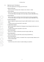
Table 2-3  3G-SDI level A video signal formats and standards 


Color System 

Quantization  Scanning 

Frame (Field) Rates 

Corresponding 

Standard 

YC

B

C

4:2:2 

10 bits 

1080p 

60/59.94/50 

SMPTE ST 424 

SMPTE ST 425 

12 bits 

1080p 

30/29.97/25/24/23.98 

1080PsF 

30/29.97/25/24/23.98 

1080i 

60/59.94/50 

YC

B

C

4:4:4 

10 bits 

1080p 

30/29.97/25/24/23.98 

1080PsF 

30/29.97/25/24/23.98 

1080i 

60/59.94/50 

720p 

60/59.94/50/30/29.97/25/24/23.98 

12 bits 

1080p 

30/29.97/25/24/23.98 

1080PsF 

30/29.97/25/24/23.98 

1080i 

60/59.94/50 

RGB 4:4:4 

10 bits 

1080p 

30/29.97/25/24/23.98 

1080PsF 

30/29.97/25/24/23.98 

1080i 

60/59.94/50 

720p 

60/59.94/50/30/29.97/25/24/23.98 

12 bits 

1080p 

30/29.97/25/24/23.98 

1080PsF 

30/29.97/25/24/23.98 

1080i 

60/59.94/50 

1080p 

24/23.98 

(2048×1080) 

1080PsF 

24/23.98 


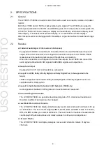
Table 2-4  3G-SDI level B video signal formats and standards 


Color System 

Quantization  Scanning 

Frame (Field) Rates 

Corresponding 

Standard 

YC

B

C

4:2:2 

10 bits 

1080p 

60/59.94/50 

SMPTE ST 424 

SMPTE ST 425 

12 bits 

1080p 

30/29.97/25/24/23.98 

1080PsF 

30/29.97/25/24/23.98 

1080i 

60/59.94/50 

YC

B

C

4:4:4 

10 bits 

1080p 

30/29.97/25/24/23.98 

1080PsF 

30/29.97/25/24/23.98 

1080i 

60/59.94/50 

12 bits 

1080p 

30/29.97/25/24/23.98 

1080PsF 

30/29.97/25/24/23.98 

1080i 

60/59.94/50 

RGB 4:4:4 

10 bits 

1080p 

30/29.97/25/24/23.98 

1080PsF 

30/29.97/25/24/23.98 

1080i 

60/59.94/50 

12 bits 

1080p 

30/29.97/25/24/23.98 

1080PsF 

30/29.97/25/24/23.98 

1080i 

60/59.94/50 

1080p 

24/23.98 

(2048×1080) 

1080PsF 

24/23.98 

USO 

RESTRITO

Summary of Contents for LV 5837

Page 1: ...LV 5838 LV 5837 AUDIO MONITOR INSTRUCTION MANUAL USO RESTRITO...

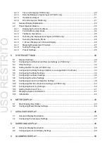
Page 2: ...Method LV 5838 only 8 2 3 3 I O Connectors 8 2 3 4 LCD 9 2 3 5 Control Connectors 9 2 3 6 Display Indication 10 2 3 7 Level Meter Display 10 2 3 8 Lissajous Display 10 2 3 9 Surround Display 11 2 3 1...

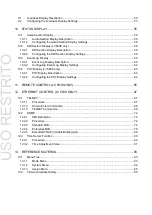
Page 3: ...V 5838 only 31 5 3 Other Settings 32 5 4 Setting the SDI Format LV 5838 only 33 5 5 Configuring the Dolby Settings Option to be supported in the future 33 5 6 Configuring the Meter Settings 34 5 7 Con...

Page 4: ...y Settings 62 10 4 PHY Display LV 5838 only 63 10 4 1 PHY Display Description 63 10 4 2 Configuring the PHY Display Settings 64 11 REMOTE CONTROL LV 5838 ONLY 65 12 ETHERNET CONTROL LV 5838 ONLY 67 12...

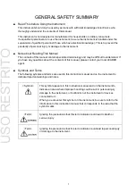
Page 5: ...If you have any questions about the contents of this manual please contact your local LEADER agent Symbols and Terms The following symbols and terms are used in this instruction manual and on the ins...

Page 6: ...the instrument has condensation within it waitfor approximately 30 minutes before turning on thepower Operating Humidity Range Use this instrument in an environment whose relative humidity is 85 or le...

Page 7: ...lead to fire We recommend you replace the AC adapter at least once every five years If You Will Not Use the Instrument for an Extended Period of Time If you will not use the instrument for an extended...

Page 8: ...ild detergent and wipe gently While cleaning make surethat foreign materials such as water and detergent do not enter the instrument If liquid or ametal object enters into the instrument fire or elect...

Page 9: ...alfunction or damages resulting from fire natural calamity orimproper voltage applied by the user 2 Repair of an instrument that has been improperly repaired adjusted or modified by personnel other th...

Page 10: ...e When you turn the power on the instrument starts with the panel settings that were in use the last time that it was turned off Ifthe backup battery is out of power the message The last memory featur...

Page 11: ...External Audio Signals Refers to digital audio signals received through the DIGITAL AUDIO connector on the rear panel Tomeasure these signals press INPUT to select AES Embedded Audio Signals Refers t...

Page 12: ...V 5838 can convert the audio signals embedded in SDI signals to AES EBU signals and output them Headphone Output Equipped with a 3 5 mm mini headphone outputjack Support for LPCM Dolby E Dolby Digital...

Page 13: ...rver LV 5838 only information Synchronous Measurement of External Reference Signals and Audio Signals LV 5838 only Synchronous measurement can be performed on a tri level signal black burst signal 10...

Page 14: ...termines the format from the input signal s synchronization information and automatically setsthe format Table 2 1 SD SDI video signal formats andstandards Color System Quantization Scanning Frame Fie...

Page 15: ...29 97 25 24 23 98 12 bits 1080p 30 29 97 25 24 23 98 1080PsF 30 29 97 25 24 23 98 1080i 60 59 94 50 1080p 24 23 98 2048 1080 1080PsF 24 23 98 Table 2 4 3G SDI level B video signal formats andstandards...

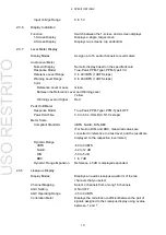
Page 16: ...C peak AC SDI Signal Output Connector LV 5838 only Output Connector 1 BNC connector Output Signal Transmits a serial reclocked signal of the signal received through the SDI signal input connector Outp...

Page 17: ...20 k Maximum Input Voltage 5 V DC peak AC LTC Input Connector LV 5838 only To be supported in the future The Dolby option will be supported in thefuture 2 3 4 LCD Type 6 3 inch color TFT Resolution V...

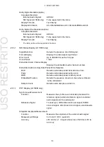
Page 18: ...r Higher Red Peak Hold Meter Response Model True Peak PPM TypeI PPM TypeII OFF Peak Hold Time 0 0 to 5 0 s HOLD 0 5 1 0 s steps Meter Scale Compliant Standard dBFS Nordic DIN BBC For Nordic DIN and BB...

Page 19: ...ockSize OverlapSize UpperThres LowerThres Absolute Level Relative Level Control Method Mono stereo 5 1 downmix custom Assign channels to L R C LFE Ls and Rs as youlike Momentary loudness short term lo...

Page 20: ...e different Validity Displays the validity bit status of the external audio signal CRC Counted as an error when the CRC value of the external audio signal and the value calculated on the LV 5837 LV 58...

Page 21: ...he embedded audio channel numbers Embedded Audio Ancillary Data Packet Error Detection BCH Detects audio data packet transmission errors Parity Detects audio data packet parity errors DBN Detects audi...

Page 22: ...ugh the Ethernet port LV5838 only or remote connector LV 5838 only Logging Feature Function Records events and loudness measurementswith timestamps Logging Method From the panel or through the Etherne...

Page 23: ...nsumption LV 5837 25 W max LV 5838 30 W max Dimensions LV 5837 215 W 128 H 72 D mm excludingprotrusions LV 5838 215 W 128 H 88 D mm excludingprotrusions Weight LV 5837 1 4 kg LV 5838 1 7 kg Accessorie...

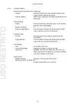
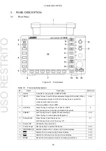
Page 24: ...LV 5837 LV 5838 Hold the key down to enable and disable the key lock 5 4 PRESET Hold the key down to register the panelsettings Press the key to recall a panel settingpreset 4 4 9 5 Power switch Press...

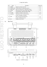
Page 25: ...EAR Hold the key down to clear loudness measurement 9 2 16 F D A function dial for configuring various settings 17 VOLUME Adjusts the headphone outputvolume 4 2 5 18 Headphone Outputs the audio of the...

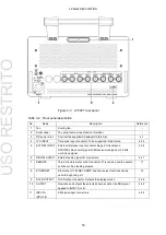
Page 26: ...el sync NTSC PAL black burst signal 10 MHz sinusoid signal or 48 kHz word clock signal 4 2 4 6 DIGITAL AUDIO External audio signal I O connectors 4 2 1 7 REMOTE 15 pin D sub remote control connector T...

Page 27: ...g the Power On To turn on the power press the power switch The power LED lights and theinstrument turns ON When you turn ON the power the LV 5837 LV 5838 starts up with the same panel settings that we...

Page 28: ...ring SDI measurement Ext AES at SDI INPUT Input Input connector Input connector Output Output connector 2 Output connector 2 1 Outputs the signal received through CH 1 2 to CH 7 8 2 Outputs embedded a...

Page 29: ...ed in the upper right of the display Reference PHONES See section 4 4 7 Mapping Measurement Channels Adjusting the Volume Use the VOLUME knob on the front panel to adjust the speaker output volume Pre...

Page 30: ...Time Server Function GENERAL tab See section 5 1 GeneralSettings 2 Time code Displays the time code when TIMECODE SETTING on the GENERAL tab in the system settings is not set to OFF Reference GENERAL...

Page 31: ...ing logged To turn event logging on and off use LOG in the status menu Reference LOG Section 10 3 2 Configuring the Event Log 9 AUDERR SDIERR Appears when an error occurs in one of the detection items...

Page 32: ...V 5837 LV 5838 immediately and contact your local LEADER agent 4 4 Panel Operation Basics 4 4 1 Displaying the Function Menu Displaying the System Menu Press SYSTEM to display the system menu press it...

Page 33: ...bs Even if you switch to another tab the settings are not confirmed until you press F 1 COMPLETE Selecting Check Boxes Move the cursor to the check box that you want to select and press the functiondi...

Page 34: ...display mode of each screen separately Table 4 2 Selecting the display mode Display Mode Description Reference METER Meters are displayed 6 LISSAJOU The Lissajous curves and meters aredisplayed 7 SUR...

Page 35: ...s measured STEREO The channels assigned to L and Rch aremeasured 5 1 The channels assigned to L R C LFE Ls and Rsch are measured 5 1_DM The channels assigned to L R C LFE Ls and Rsch as well as Lt and...

Page 36: ...til the message KEYLOCK Canceled appears on thescreen 4 4 9 Preset Settings You can register up to five panel setting presets Registered presets are not initialized when you press SYSTEM and then F 7...

Page 37: ...date that is shown in the upper left of the screen Select off to hide the date Time ON OFF Turn the time display in the upper left of the screen on oroff Video Format ON OFF LV 5838 only Turn the form...

Page 38: ...ATC VITC ATC D_VITC AESEBU LTC EXT Select the display format for the time code that is shown in the upper left of the screen This also applies to various types of log data You can only select OFF or A...

Page 39: ...setautomatically This setting is enabled after you restart the LV5838 Time Server ON OFF Select whether to enable the time server function When set to ON set to the IP address of the time server in I...

Page 40: ...15 Set the backlight brightness The larger the number the darker thebacklight When you change the value the brightness changes for verification but it will not be applied until you press F 1 COMPLETE...

Page 41: ...PsF Select Interlace Segmented Frame Select the display format that is shown at the top of thescreen 5 5 Configuring the Dolby Settings Option to be supported in the future To configure the Dolby set...

Page 42: ...red if this value is exceeded Reference Index 40 20 0 dBFS Set the reference level Meters are normally displayed in green but they are displayed in yellow when levels are between the Reference Index a...

Page 43: ...S1770 2 ARIB EBU ATSC CUSTOM Target Level 24 LKFS 24 LKFS 23 LUFS 24 LKFS 99 to 0 LKFS LFE Gain 0 0 0 0 0 0 0 0 0 0 to 10 0 BlockSize ms 400 400 400 400 200 to 30000 OverlapSize 75 75 75 0 0 to 99 Upp...

Page 44: ...and clear and storage to USB memory are executed at the following times Enter a value for StopTime If you select CM CM appears in the upper right of the screen Press START PAUSE and then apply the ma...

Page 45: ...e the DOWNMIX tab These settings are valid when GROUP1 or GROUP2 is set to 5 1_DM on the assign menu BEHAVIOR SETUP NEXT TAB 4 Figure 5 10 DOWNMIX tab DOWNMIX Coefficient 1 2 1 2 1 2 2 0 Select the do...

Page 46: ...for detecting errors LevelOver ON OFF Level 40 0 dBFS Turn the level over error detection on or off If you select ON enter the level An error is detected when a signal exceeding the specified level i...

Page 47: ...n the parity bit of the input signal and the value calculated on the LV 5837 LV 5838 are different Validity ON OFF Turn the validity error detection on or off An error is detected when the validity bi...

Page 48: ...the event log display Reference See section 10 2 SDI Section Display LV 5838 only and section 10 3 Event Log Display BEHAVIOR SETUP PREV TAB 2 Figure 5 12 SDI ERROR tab 5 11 Configuring Event Log Set...

Page 49: ...he date and time that are shown in the upper left of the screen TIME SETUP Figure 5 14 TIME tab 5 13 Displaying System Information You can view system information on the INFORMATION tab You can check...

Page 50: ...emote settings ETHER REMOTE tab LV 5838 only No Yes Preset contents No Yes Date and time settings TIME tab No No Yes Initialized No Not initialized Configuration Initialization To perform configuratio...

Page 51: ...displayed when 16 channels aredisplayed 2 Level display The current level is displayed 3 Peak Display The peak value is displayed when PEAKHOLD is not set to OFF 4 Error Level Display The error level...

Page 52: ...or details on the METER 1 tab see section 5 4 Configuring the Meter Settings DISPLAY to METER METER SETUP Figure 6 2 METER SETUP menu RESPONSE TRUEPEAK PPM I PPM II VU Select the meter response model...

Page 53: ...7 dB Reference Index 1 25 dB GROUP GROUP1 GROUP2 ALL 1 8 9 16 Select the display channels Reference GROUP1 GROUP2 See section 4 4 7 Mapping MeasurementChannels GROUP1 Channels that were selected using...

Page 54: ...ter channels are assigned on the assign menu Figure 7 1 Lissajous display 1 L The channel assigned using LCH is displayed 2 R The channel assigned using RCH is displayed 3 Correlation meter The correl...

Page 55: ...0 dBFS GROUP GROUP1 GROUP2 ALL 1 8 9 16 Select the display channels Reference GROUP1 GROUP2 See section 4 4 7 Mapping MeasurementChannels GROUP1 In the meter display channels that were selected using...

Page 56: ...creen and level meters are displayed on the right half of the screen Channels are assigned onthe assign menu Figure 8 1 Surround display 1 Surround display A surround waveform and Lissajous curves of...

Page 57: ...om center and a Cch hard center waveform are displayed separately METER SETUP Configure the meter settings For a description of the settings see section6 2 Configuring the Meter Display Settings Howev...

Page 58: ...OUDNESS 9 1 Loudness Display Description In the loudness display you can press F 1 DISPLAY to switch the display format between chart loudness meter and numeric Channels are assigned on the assign men...

Page 59: ...9 LOUDNESS DISPLAY 51 DISPLAY NUM Figure 9 3 Numeric display DISPLAY METER Figure 9 4 Meter display F 1 F 1 USO RESTRITO...

Page 60: ...e is an absolute value The bottom value is a relative value with the target level as the reference Only the relative value is displayed in the meter display 6 I The integrated loudness is displayed Th...

Page 61: ...isplayed in the upper right ofthe screen when measurement is in progress This key is valid regardless of the display mode USB STORE Press this key to store a loudness log to a USB memory device in CSV...

Page 62: ...he loudnessdisplay VERT Loudness meters displayed vertically and the chart are displayed side by side HORI Loudness meters displayed horizontally and the chart are displayed top and bottom SCALE MAG O...

Page 63: ...or Count Display The LV 5837 LV 5838 counts errors for the items that are enabled on the AUDIO ERROR tab in the system settings except for validity which is always counted Errors are counted up to 999...

Page 64: ...Use F 6 ALIGN to change the bit order of binary values DISPLAY CH STATUS Figure 10 2 Channel status display User Bit Display The user bit display shows the user bits for the channels that you have se...

Page 65: ...display shows meta data during Dolby measurement DISPLAY DOLBY META Figure 10 4 Dolby metadata display Dolby EBI Data Display option to be supported in the future The EBI data display shows EBI data...

Page 66: ...BIT DOLBY META DOLBY EBI Select the display format of the audio section display AUD STATUS The error count is displayed CH STATUS The channel status is displayed USERBIT User bits are displayed DOLBY...

Page 67: ...are counted up to 999 999 You can clear the counters using F 4 ERROR CLEAR Reference AUDIO ERROR tab See 5 8 Configuring Error Detection Settings Figure 10 7 SDI section display 10 2 2 Configuring th...

Page 68: ...g display Time Display On the GENERAL tab in the system settings set TIMECODE SETTING to OFF to log events using the current time or some other setting to log events using the time codes embedded in t...

Page 69: ...ror A_INH Inhibit Error A_SMP Sample Number Error Following the error name on the AUDIO ERROR tab the channels on which the error occurred are displayed using a hexadecimal number for example MUTE 000...

Page 70: ...MODE to EVENTLOG Figure 10 10 STATUS SETUP menu USBSTORE Save the event log as a text file to a USB memory device This key appears when a USB memory device is connected to the LV 5837 LV5838 Log files...

Page 71: ...s performed on external audio signals and displayed This does not appear during SDImeasurement Sync The frequency measurement results are displayed as OK or NG A yellow OK is displayed for the referen...

Page 72: ...ATUS SETUP menu F 2 SOURCE CH1 2 CH3 4 CH5 6 CH7 8 CH9 10 CH11 12 CH13 14 CH15 16 EXT SYNC Select the signal to use as the frequency measurement reference If you select EXT SYNC select the format on t...

Page 73: ...2 tab in the system settings to Remote Connect a LV 5838 02 to control these operations usingbuttons 3 G1 and G2 indicate GROUP1 and GROUP2 on the assign menu Connect a LV 5838 01 to control these op...

Page 74: ...ot apply negative voltagesor voltages that exceed 5 V The active low signal must be stable for at least 350 ms After that wait at least 1 second before applying the nextsignal Figure 11 3 Remote contr...

Page 75: ...remotely control mostof the operations that can be controlled from thepanel 12 1 1 Procedure 1 On the ETHER REMOTE tab set the IP address Reference See section 5 2 Configuring the Ethernet and Remote...

Page 76: ...mark as the parameter Examples of how to enter commands are shown below You can enter commands using uppercase or lowercase letters Commands that begin with MODE only apply to the area 1 or 2 that is...

Page 77: ...CH16 DOLBY1 to DOLBY8 DOLBY_AUX ASSIGN PHONES_R CH1 to CH16 DOLBY1 to DOLBY8 DOLBY_AUX ASSIGN AUX_CH LT RT LO RO MONO MUTE ASSIGN AUX_CH_DRC LINE RF ASSIGN GROUP1 L CH1 to CH16 NON_CONNECT ASSIGN GRO...

Page 78: ...MAG OFF WIDE NARROW MODE LOUDNESS GROUP GROUP1 GROUP2 MODE STATUS MODE AUD SEC SDI SEC EVENTLOG PHY MODE STATUS DISPLAY AUD STATUS CH STATUS USERBIT DOLBY META DOLBY EBI MODE STATUS SCALE 50MS 100MS 5...

Page 79: ...T FLAG ON OFF SYSTEM ERROR SILENT DURATION 1 to 5000 in steps of 10 SYSTEM ERROR FRAME FLAG ON OFF SYSTEM ERROR FRAME GUARDBAND RDD6 CUSTOM SYSTEM ERROR FRAME SD_MIN 8 to 30 SYSTEM ERROR FRAME SD_MAX...

Page 80: ...yString FROM SNMPv2 TC OBJECT GROUP MODULE COMPLIANCE FROM SNMPv2 CONF 12 2 2 Procedure 1 Configure the Ethernet settings on the ETHER REMOTE tab of the LV5838 Set the IP Address set SNMP to ON ACCESS...

Page 81: ...3 6 1 4 1 leader 20111 lv5838 25 lv5838ST1 1 l25trapTBL 5 l25trapIpTBL 2 l25t rapIp4TBL 4 l25trapManagerIp4 1 0 8 Enable the TRAP transmission destinations To alleviate communication load disable the...

Page 82: ...sUpTime system 3 TimeTicks R O sysContact 1 system 4 DisplayString R W sysName 1 system 5 DisplayString R W sysLocation 1 system 6 DisplayString R W sysServices system 7 INTEGER R O 1 Set using up to...

Page 83: ...iscards ip 11 Counter R O ipOutNoRoutes ip 12 Counter R O ipReasmTimeout ip 13 INTEGER R O ipReasmReqds ip 14 Counter R O ipReasmOKs ip 15 Counter R O ipReasmFails ip 16 Counter R O ipFragOKs ip 17 Co...

Page 84: ...ipForwardTable 1 INTEGER R O Table 12 8 icmp group MIB OID SYNTAX ACCESS SUPPORT icmpInMsgs icmp 1 Counter R O icmpInErrors icmp 2 Counter R O icmpInDestUnreachs icmp 3 Counter R O icmpInTimeExcds icm...

Page 85: ...Entry 1 INTEGER R O tcpConnLocalAddress tcpConnEntry 2 IpAddress R O tcpConnLocalPort tcpConnEntry 3 INTEGER R O tcpConnRemAddress tcpConnEntry 4 IpAddress R O tcpConnRemPort tcpConnEntry 5 INTEGER R...

Page 86: ...etRequests snmp 15 Counter R O snmpInGetNexts snmp 16 Counter R O snmpInSetRequests snmp 17 Counter R O snmpInGetResponses snmp 18 Counter R O snmpInTraps snmp 19 Counter R O snmpOutTooBigs snmp 20 Co...

Page 87: ...ome Ver 21 0 Figure 12 3 Entering the IP address When the following page appears right click DOWNLOAD and click Save Link As Check that the extension is my If it is set to any other extension specify...

Page 88: ...in2 l25plMulti l25panelTBL 4 INTEGER R W 1 single 2 multi l25plLoudness l25panelTBL 5 INTEGER R W 1 start 2 pause Table 12 13 l25assignTBL 2 group MIB OID SYNTAX ACCESS VALUE RANGE l25assignModeGroup1...

Page 89: ...tted 16 ch16 17 non_connect l25assignGroup1Lfe l25assignGroup1TBL 4 INTEGER R W 1 ch1 Omitted 16 ch16 17 non_connect l25assignGroup1Ls l25assignGroup1TBL 5 INTEGER R W 1 ch1 Omitted 16 ch16 17 non_con...

Page 90: ...ound 4 loudness 5 status l25modeMeterTBL l25modeTBL 2 Aggregate l25modeMeterResponse l25modeMeterTBL 1 INTEGER R W 1 truepeak 2 ppm1 3 ppm2 4 vu l25modeMeterPeakHold l25modeMeterTBL 2 INTEGER R W 1 of...

Page 91: ...5modeSurrTBL 1 INTEGER R W 1 both 2 lissajou 3 surround l25modeSurrMode l25modeSurrTBL 2 INTEGER R W 1 normal 2 phantom l25modeSurrAutoGain l25modeSurrTBL 3 INTEGER R W 1 on 2 off l25modeSurrGroup l25...

Page 92: ...50ms 2 100ms 3 500ms 4 1 0s 5 2 5s l25modeStatusSource l25modeStatusTBL 4 INTEGER R W 1 aesebu 2 sdi_anc l25modeStatusChStatusTBL l25modeStatusTBL 5 Aggregate l25modeStatusChStatusCh l25modeStatusChS...

Page 93: ...in l25sysLoudTBL 3 STRING R W 0 to 10 in steps of 0 5 l25sysLoudBlockSize l25sysLoudTBL 4 STRING R W 200 to 30000 in steps of 50 l25sysLoudOverlapSize l25sysLoudTBL 5 STRING R W 0 to 99 l25sysLoudAbso...

Page 94: ...STRING R W 8 to 30 l25sysErrorFrameSdMax l25sysErrorTBL 13 STRING R W 8 to 30 l25sysErrorFrameHdMin l25sysErrorTBL 14 STRING R W 8 to 30 l25sysErrorFrameHdMax l25sysErrorTBL 15 STRING R W 8 to 30 l25s...

Page 95: ...apStrTBL l25trapTBL 1 Aggregate Variable BindingList l25trapIpTBL l25trapTBL 2 Aggregate l25trapIp1TBL l25trapIpTBL 1 Aggregate l25trapManagerIp1 l25trapIp1TBL 1 IpAddress R W Trap transmission destin...

Page 96: ...8 ONLY 88 MIB OID SYNTAX ACCESS VALUE RANGE l25trapManagerIp4 l25trapIp4TBL 1 IpAddress R W Trap transmission destination manager IP address 4 l25trapManagerIp4Act l25trapIp4TBL 2 IpAddress R W 1 disa...

Page 97: ...Format information Example 1080sF 30 index 4 OID leader 20111 lv5838 25 lv5838ST1 1 trapTBL 5 trapStrTBL 1 4 0 Syntax Octet String Range Up to 40 characters Description Error information see the table...

Page 98: ...12 ETHERNET CONTROL LV 5838 ONLY 90 26 AUD_VALIDITY_ERR AUDIO Validity error detection USO RESTRITO...

Page 99: ...V 5838 only SYSTEM SETUP NEXT TAB Figure 12 5 ETHER REMOTE tab 2 Press COMPLETE 3 Restart the LV 5838 If you didn t make any changes you do not have torestart 4 Connect the Ethernet port on the rear p...

Page 100: ...and 03 00 Brazil Fernando de Noronha 02 00 Azores Cape Verde 01 00 United Kingdom Ireland Portugal Iceland Morocco East Africa Ghana etc 00 00 Central European Time France Germany etc West Africa Time...

Page 101: ...12 ETHERNET CONTROL LV 5838 ONLY 92 Country or region Time Zone Kiribati Line Islands Tokelau 14 00 USO RESTRITO...

Page 102: ...D SCALE MAG OFF ON GROUP GROUP1 GROUP2 ALL 1 8 9 16 LISSAJOU SETUP UP MENU LCH CH 1 CH16 D1 D8 Lt RCH METER SETUP CH 1 CH16 D1 D8 Rt AUTOGAIN ON OFF GROUP UP MENU GROUP1 GROUP2 ALL 1 8 9 16 SURROUND S...

Page 103: ...11 12 CH13 14 CH15 16 EXT SYNC LOG STOP START ERROR CLEAR LOG CLEAR ALIGN LSB 1st MSB 1st UP MENU 13 1 2 System Menu SYSTEM SETUP COMPLETE PREV TAB NEXT TAB BEHAVIOR SETUP UP MENU COMPLETE PREV TAB NE...

Page 104: ...V TAB NEXT TAB UP MENU PHONES L 1 16 D1 D8 DAUX PHONES R 1 2 16 D1 D8 DAUX AUX CH LT RT LO RO MONO MUTE AUX CH DRC LINE RF 13 2 Firmware Update History This manual was written for firmware version 1 1...

Page 105: ...Following information is for Chinese RoHS only LV 5837 LV 5838 2006 2 28 SJ T11364 2006 Parts Hazardous Substances in each Part Pb Hg Cd Cr PBB PBDE SJ T11363 2006 SJ T11363 2006 Ver 2 USO RESTRITO...

Page 106: ...LEADER ELECTRONICS CORP 2 6 33 Tsunashima Higashi Kohoku ku Yokohama 223 8505 Japan PHONE 81 45 541 2123 FAX 81 45 541 2823 http www leader co jp Oct 16 2012 Ver 1 FW Ver 1 1 USO RESTRITO...

Reviews: