44
6. METER DISPLAY
F
•1
F•2
F•2
F•1
F•2
F•3
F•4
6
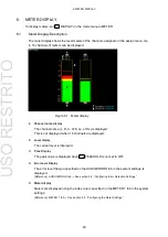
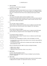
Channel display
The channel (1 to 16) is displayed.
“X” is displayed for channels whose CHANNEL
SETTING on the assign menu has been set to Non Connect.
[Reference] CHANNEL SETTING → See section 4.4.7, “Mapping Measurement Channels.”
7
RESPONSE
The response model that you selected with
RESPONSE is displayed.
8
PEAKHOLD
The response model that you selected with
PEAKHOLD is displayed.
6.2
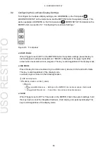
Configuring Meter Display Settings
To
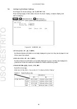
configure the meter display settings, use F•2 METER SETUP on the mode menu and the
METER 1 tab in the system settings. This section explains F•2 METER SETUP. For details
on the METER 1 tab, see section 5.4,
“Configuring the Meter Settings.”
→
DISPLAY to METER
→
METER SETUP
→
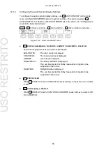
Figure 6-2 METER SETUP menu
●
RESPONSE: TRUEPEAK / PPM(I) / PPM(II) / VU
Select the meter response model. The selected response model is indicated in the lower
right of the screen.
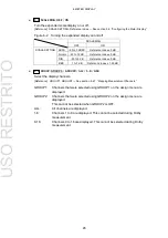
Table 6-1 Selecting the response model
Attack Time
Return Time
Average Time
RESPONSE TRUEPEAK
0 s
1.7 s
-
PPM(I)
10 ms
1.7 s
-
PPM(II)
10 ms
2.8 s
-
VU
-
-
300 ms
●
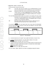
PEAKHOLD: OFF / TRUEPEAK / PPM(I) / PPM(II)
Select the response model of the peak hold meter. The selected response model is
indicated in the lower right of the screen.
●
PEAKHOLD TIME: 0.0 / 0.5 / 1.0 / 2.0 / 3.0 / 4.0 / 5.0 / HOLD
If
PEAKHOLD is not set to OFF, select the peak value hold time in seconds.
●
PEAKHOLD RESET
If
PEAKHOLD is not set to OFF, press this key to reset the peak value.
F•1
F•2
F
•2
MODE
USO
RESTRITO


